
Page 136 - Optical Communications Essentials
P. 136
Connectors and Splices
126 Chapter Eight
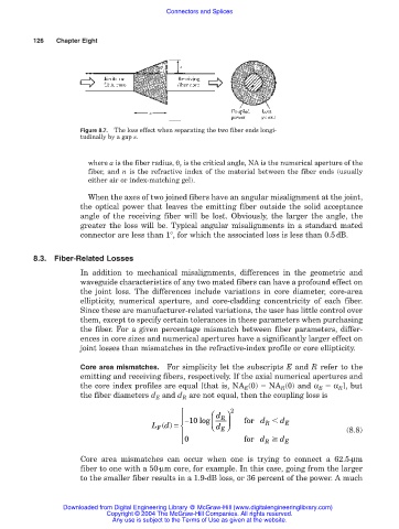
Figure 8.7. The loss effect when separating the two fiber ends longi-
tudinally by a gap s.
where a is the fiber radius, θ c is the critical angle, NA is the numerical aperture of the
fiber, and n is the refractive index of the material between the fiber ends (usually
either air or index-matching gel).
When the axes of two joined fibers have an angular misalignment at the joint,
the optical power that leaves the emitting fiber outside the solid acceptance
angle of the receiving fiber will be lost. Obviously, the larger the angle, the
greater the loss will be. Typical angular misalignments in a standard mated
connector are less than 1°, for which the associated loss is less than 0.5dB.
8.3. Fiber-Related Losses
In addition to mechanical misalignments, differences in the geometric and
waveguide characteristics of any two mated fibers can have a profound effect on
the joint loss. The differences include variations in core diameter, core-area
ellipticity, numerical aperture, and core-cladding concentricity of each fiber.
Since these are manufacturer-related variations, the user has little control over
them, except to specify certain tolerances in these parameters when purchasing
the fiber. For a given percentage mismatch between fiber parameters, differ-
ences in core sizes and numerical apertures have a significantly larger effect on
joint losses than mismatches in the refractive-index profile or core ellipticity.
Core area mismatches. For simplicity let the subscripts E and R refer to the
emitting and receiving fibers, respectively. If the axial numerical apertures and
the core index profiles are equal [that is, NA E (0) NA R (0) and α E α R ], but
the fiber diameters d E and d R are not equal, then the coupling loss is
d 2
−10 log R for d d
Ld() = d R E
F
E
(8.8)
0 for d d E
R
Core area mismatches can occur when one is trying to connect a 62.5-µm
fiber to one with a 50-µm core, for example. In this case, going from the larger
to the smaller fiber results in a 1.9-dB loss, or 36 percent of the power. A much
Downloaded from Digital Engineering Library @ McGraw-Hill (www.digitalengineeringlibrary.com)
Copyright © 2004 The McGraw-Hill Companies. All rights reserved.
Any use is subject to the Terms of Use as given at the website.