
Page 132 - Optical Communications Essentials
P. 132
Connectors and Splices
122 Chapter Eight
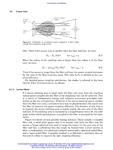
Figure 8.3. Schematic of an optical source coupled to a fiber. Light
outside the acceptance angle is lost.
fiber. Then if the source area is smaller than the fiber end face, we have
P F P S (NA) 2 for r LED a (8.2)
When the radius of the emitting area is larger than the radius a of the fiber
core, we have
2
P F (a/r LED ) P S (NA) 2 for r LED a (8.3)
Thus if the source is larger than the fiber end face, the power coupled decreases
by the ratio of the fiber-to-source areas. The ratio P F /P S is defined as the cou-
pling efficiency.
For detailed power coupling calculations, the reader is referred to the book
Optical Fiber Communications, by Keiser.
8.1.3. Lensed fibers
If a source emitting area is larger than the fiber core area, then the resulting
optical power coupled into the fiber is the maximum that can be achieved. This
is a result of fundamental energy and radiance conversion principles (also
known as the law of brightness). However, if the source emitting area is smaller
than the fiber core area, a miniature lens may be placed between the source and
the fiber to improve the power coupling efficiency. The function of this lens is
to magnify the source emitting area to match exactly the core area of the fiber
end face. If the emitting area is increased by a magnification factor M, the solid
angle within which optical power is coupled to the fiber is increased by the same
factor.
Figure 8.4 shows several possible lensing schemes. These include a rounded
fiber end, a small glass sphere that is in contact with both the fiber and the
source, a larger spherical lens used to image the source on the core area of the
fiber end face, a cylindrical lens that might be formed from a short section of
fiber, a combination of a spherical-surfaced source and a spherical-ended fiber,
and a taper-ended fiber. A popular method is to fabricate a miniature lens on
the end of a fiber to improve the light coupling efficiency.
Downloaded from Digital Engineering Library @ McGraw-Hill (www.digitalengineeringlibrary.com)
Copyright © 2004 The McGraw-Hill Companies. All rights reserved.
Any use is subject to the Terms of Use as given at the website.