
Page 131 - Optical Communications Essentials
P. 131
Connectors and Splices
Connectors and Splices 121
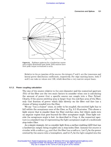
Figure 8.2. Radiance patterns for a lambertian source
and a highly directional laser diode. Both sources have
their peak output normalized to unity.
Relative to the pn junction of the source, the integers T and L are the transverse and
lateral power distribution coefficients, respectively. For edge emitting lasers, both T
and L can take on values over 100, which describes a very narrow output beam.
8.1.2. Power coupling calculation
The size of the source relative to the core diameter and the numerical aperture
(NA) of the fiber are the two main factors to consider when one is calculating
the amount of power that a specific source can couple into a fiber flylead.
Clearly, if the source emitting area is larger than the end-face area of the fiber,
only that fraction of power which falls directly on the fiber end face has a
chance of being coupled into the fiber.
We say “has a chance” since, in order to be coupled, the emitted light has to
fall within the acceptance cone of the fiber, as Fig. 8.3 illustrates. This shows a
light source that is smaller than the fiber end-face area, but which emits into
an angular region that goes beyond the fiber acceptance angle. Thus light out-
side the acceptance angle is lost. As described in Chap. 4, the numerical aper-
ture is a standard way of representing the light acceptance angle of a multimode
step-index fiber.
As a simple example, let us consider light from a surface emitting LED that has
a lambertian output being coupled into a step-index fiber. Assume the source is
circular with a radius r LED and that the fiber has a radius a. Let P S be the power
emitted by the source into a hemisphere, and let P F be the light coupled into the
Downloaded from Digital Engineering Library @ McGraw-Hill (www.digitalengineeringlibrary.com)
Copyright © 2004 The McGraw-Hill Companies. All rights reserved.
Any use is subject to the Terms of Use as given at the website.