
Page 134 - Optical Communications Essentials
P. 134
Connectors and Splices
124 Chapter Eight
8.2. Mechanics of Fiber Joints
A significant factor in any fiber optic system installation is the requirement to
interconnect fibers in a low-loss manner. These interconnections occur at the
optical source, at the photodetector, at intermediate points within a cable where
two fibers join, and at intermediate points in a link where two cables are
connected. The particular technique selected for joining the fibers depends
on whether a permanent bond or an easily demountable connection is desired.
A permanent bond (usually within a cable) is referred to as a splice, whereas
a demountable joint at the end of a cable is known as a connector.
Every joining technique is subject to certain conditions that can cause vary-
ing degrees of optical power loss at the joint. These losses depend on factors
such as the mechanical alignments of the two fibers, differences in the geomet-
ric and waveguide characteristics of the two fiber ends at the joint, and the fiber
end-face qualities. This section looks at mechanical factors, and Sec. 8.3 ad-
dresses fiber-related losses.
8.2.1. Mechanical misalignments
The core of a standard multimode fiber nominally is 50 to 100µm in diameter,
which is equivalent to the thickness of a human hair (without body-enhancing
gel). Single-mode fibers have core diameters on the order of 9µm. This is about
the size of the soft underbelly down hair of Himalayan mountain goats, which
is used to make fashionable pashmina fabrics. Owing to this microscopic size,
mechanical misalignment is a major challenge in joining two fibers. Power
losses result from misalignments because the radiation cone of the emitting
fiber does not match the acceptance cone of the receiving fiber. The magnitude
of the power loss depends on the degree of misalignment.
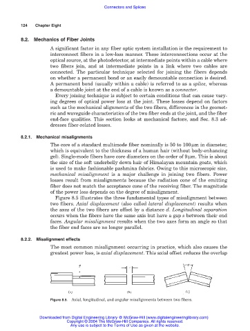
Figure 8.5 illustrates the three fundamental types of misalignment between
two fibers. Axial displacement (also called lateral displacement) results when
the axes of the two fibers are offset by a distance d. Longitudinal separation
occurs when the fibers have the same axis but have a gap s between their end
faces. Angular misalignment results when the two axes form an angle so that
the fiber end faces are no longer parallel.
8.2.2. Misalignment effects
The most common misalignment occurring in practice, which also causes the
greatest power loss, is axial displacement. This axial offset reduces the overlap
Figure 8.5. Axial, longitudinal, and angular misalignments between two fibers.
Downloaded from Digital Engineering Library @ McGraw-Hill (www.digitalengineeringlibrary.com)
Copyright © 2004 The McGraw-Hill Companies. All rights reserved.
Any use is subject to the Terms of Use as given at the website.