
Page 139 - Optical Communications Essentials
P. 139
Connectors and Splices
Connectors and Splices 129
Figure 8.9. Controlled-fracture technique for cleaving fibers.
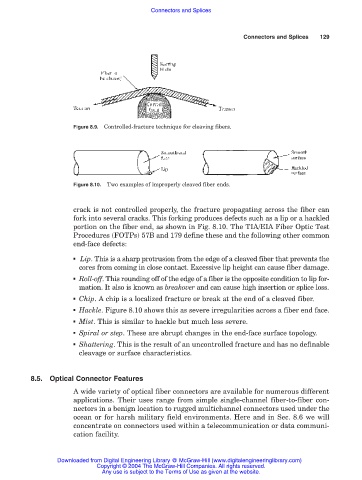
Figure 8.10. Two examples of improperly cleaved fiber ends.
crack is not controlled properly, the fracture propagating across the fiber can
fork into several cracks. This forking produces defects such as a lip or a hackled
portion on the fiber end, as shown in Fig. 8.10. The TIA/EIA Fiber Optic Test
Procedures (FOTPs) 57B and 179 define these and the following other common
end-face defects:
■ Lip. This is a sharp protrusion from the edge of a cleaved fiber that prevents the
cores from coming in close contact. Excessive lip height can cause fiber damage.
■ Roll-off. This rounding off of the edge of a fiber is the opposite condition to lip for-
mation. It also is known as breakover and can cause high insertion or splice loss.
■ Chip. A chip is a localized fracture or break at the end of a cleaved fiber.
■ Hackle. Figure 8.10 shows this as severe irregularities across a fiber end face.
■ Mist. This is similar to hackle but much less severe.
■ Spiral or step. These are abrupt changes in the end-face surface topology.
■ Shattering. This is the result of an uncontrolled fracture and has no definable
cleavage or surface characteristics.
8.5. Optical Connector Features
A wide variety of optical fiber connectors are available for numerous different
applications. Their uses range from simple single-channel fiber-to-fiber con-
nectors in a benign location to rugged multichannel connectors used under the
ocean or for harsh military field environments. Here and in Sec. 8.6 we will
concentrate on connectors used within a telecommunication or data communi-
cation facility.
Downloaded from Digital Engineering Library @ McGraw-Hill (www.digitalengineeringlibrary.com)
Copyright © 2004 The McGraw-Hill Companies. All rights reserved.
Any use is subject to the Terms of Use as given at the website.