
Page 135 - Optical Communications Essentials
P. 135
Connectors and Splices
Connectors and Splices 125
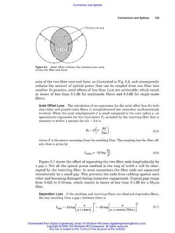
Figure 8.6. Axial offset reduces the common-core area
of the two fiber end faces.
area of the two fiber-core end faces, as illustrated in Fig. 8.6, and consequently
reduces the amount of optical power that can be coupled from one fiber into
another. In practice, axial offsets of less than 1 µm are achievable, which result
in losses of less than 0.1 dB for multimode fibers and 0.3 dB for single-mode
fibers.
Axial Offset Loss The calculation of an expression for the axial offset loss for both
step-index and graded-index fibers is straightforward but somewhat mathematically
involved. When the axial misalignment d is small compared to the core radius a, an
approximate expression for the total power P T accepted by the receiving fiber that is
accurate to within 1 percent for d/a 0.4 is
8 d
P ≈ P 1 −
T 3π a (8.5)
where P is the power emerging from the emitting fiber. The coupling loss for fiber off-
sets then is given by
P T
L offset =−10 log (8.6)
P
Figure 8.7 shows the effect of separating the two fiber ends longitudinally by
a gap s. Not all the optical power emitted in the ring of width x will be inter-
cepted by the receiving fiber. In most connectors the fiber ends are separated
intentionally by a small gap. This prevents the ends from rubbing against each
other and becoming damaged during connector engagement. Typical gaps range
from 0.025 to 0.10mm, which results in losses of less than 0.1dB for a 50-µm
fiber.
Separation Loss If the emitting and receiving fibers are identical step-index fibers,
the loss resulting from a gap s between them is
a 2 a 2
L gap =−10 log =−10 log (8.7)
+
astan+ c asarcsin(NA/ n)
Downloaded from Digital Engineering Library @ McGraw-Hill (www.digitalengineeringlibrary.com)
Copyright © 2004 The McGraw-Hill Companies. All rights reserved.
Any use is subject to the Terms of Use as given at the website.