
Page 130 - Optical Communications Essentials
P. 130
Connectors and Splices
120 Chapter Eight
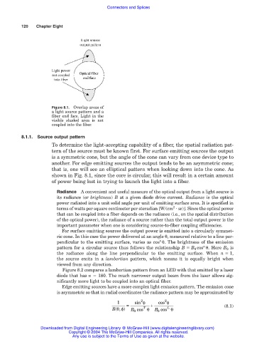
Figure 8.1. Overlap areas of
a light source pattern and a
fiber end face. Light in the
visible shaded area is not
coupled into the fiber.
8.1.1. Source output pattern
To determine the light-accepting capability of a fiber, the spatial radiation pat-
tern of the source must be known first. For surface emitting sources the output
is a symmetric cone, but the angle of the cone can vary from one device type to
another. For edge emitting sources the output tends to be an asymmetric cone;
that is, one will see an elliptical pattern when looking down into the cone. As
shown in Fig. 8.1, since the core is circular, this will result in a certain amount
of power being lost in trying to launch the light into a fiber.
Radiance A convenient and useful measure of the optical output from a light source is
its radiance (or brightness) B at a given diode drive current. Radiance is the optical
power radiated into a unit solid angle per unit of emitting surface area. It is specified in
2
terms of watts per square centimeter per steradian [W/(cm sr)]. Since the optical power
that can be coupled into a fiber depends on the radiance (i.e., on the spatial distribution
of the optical power), the radiance of a source rather than the total output power is the
important parameter when one is considering source-to-fiber coupling efficiencies.
For surface emitting sources the output power is emitted into a circularly symmet-
ric cone. In this case the power delivered at an angle θ, measured relative to a line per-
n
pendicular to the emitting surface, varies as cos θ. The brightness of the emission
n
pattern for a circular source thus follows the relationship B B 0 cos θ. Here B 0 is
the radiance along the line perpendicular to the emitting surface. When n 1,
the source emits in a lambertian pattern, which means it is equally bright when
viewed from any direction.
Figure 8.2 compares a lambertian pattern from an LED with that emitted by a laser
diode that has n 180. The much narrower output beam from the laser allows sig-
nificantly more light to be coupled into an optical fiber.
Edge emitting sources have a more complex light emission pattern. The emission cone
is asymmetric so that in radial coordinates the radiance pattern may be approximated by
2
2
1 = sin φ + cos φ
B(θφ ) B cos θ B cos θ (8.1)
T
L
,
0
0
Downloaded from Digital Engineering Library @ McGraw-Hill (www.digitalengineeringlibrary.com)
Copyright © 2004 The McGraw-Hill Companies. All rights reserved.
Any use is subject to the Terms of Use as given at the website.