
Page 133 - Optical Communications Essentials
P. 133
Connectors and Splices
Connectors and Splices 123
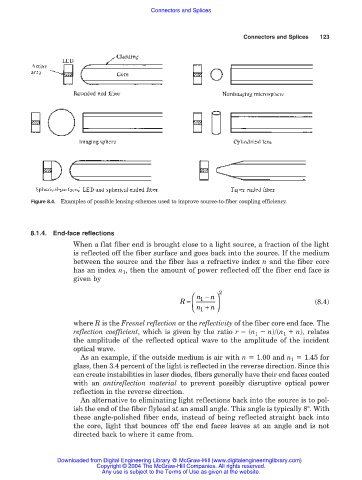
Figure 8.4. Examples of possible lensing schemes used to improve source-to-fiber coupling efficiency.
8.1.4. End-face reflections
When a flat fiber end is brought close to a light source, a fraction of the light
is reflected off the fiber surface and goes back into the source. If the medium
between the source and the fiber has a refractive index n and the fiber core
has an index n 1 , then the amount of power reflected off the fiber end face is
given by
n − 2
n
R = 1 (8.4)
n +
1 n
where R is the Fresnel reflection or the reflectivity of the fiber core end face. The
reflection coefficient, which is given by the ratio r (n 1 n)/(n 1 n), relates
the amplitude of the reflected optical wave to the amplitude of the incident
optical wave.
As an example, if the outside medium is air with n 1.00 and n 1 1.45 for
glass, then 3.4 percent of the light is reflected in the reverse direction. Since this
can create instabilities in laser diodes, fibers generally have their end faces coated
with an antireflection material to prevent possibly disruptive optical power
reflection in the reverse direction.
An alternative to eliminating light reflections back into the source is to pol-
ish the end of the fiber flylead at an small angle. This angle is typically 8°. With
these angle-polished fiber ends, instead of being reflected straight back into
the core, light that bounces off the end faces leaves at an angle and is not
directed back to where it came from.
Downloaded from Digital Engineering Library @ McGraw-Hill (www.digitalengineeringlibrary.com)
Copyright © 2004 The McGraw-Hill Companies. All rights reserved.
Any use is subject to the Terms of Use as given at the website.