
Page 15 - Optical Communications Essentials
P. 15
Basic Concepts of Communication Systems
Basic Concepts of Communication Systems 5
Amplitude
0 Time
1/f Period = 1/f 1/f
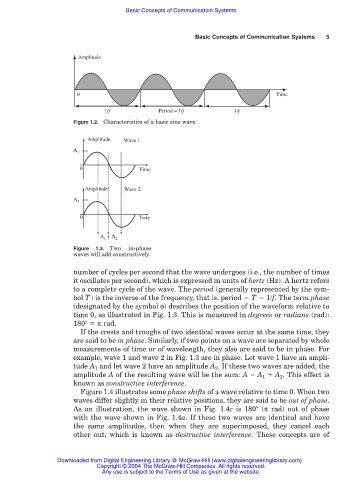
Figure 1.2. Characteristics of a basic sine wave.
Amplitude Wave 1
Wave 1
A A 1 1
0 Time
Wave 2
Amplitude Wave 2
A 2
A 2
0 Time
A
A 1 + A 21 + A 2
Figure 1.3. Two in-phase
waves will add constructively.
number of cycles per second that the wave undergoes (i.e., the number of times
it oscillates per second), which is expressed in units of hertz (Hz). A hertz refers
to a complete cycle of the wave. The period (generally represented by the sym-
bol T) is the inverse of the frequency, that is, period T 1/f. The term phase
(designated by the symbol φ) describes the position of the waveform relative to
time 0, as illustrated in Fig. 1.3. This is measured in degrees or radians (rad):
180° π rad.
If the crests and troughs of two identical waves occur at the same time, they
are said to be in phase. Similarly, if two points on a wave are separated by whole
measurements of time or of wavelength, they also are said to be in phase. For
example, wave 1 and wave 2 in Fig. 1.3 are in phase. Let wave 1 have an ampli-
tude A 1 and let wave 2 have an amplitude A 2 . If these two waves are added, the
amplitude A of the resulting wave will be the sum: A A 1 A 2 . This effect is
known as constructive interference.
Figure 1.4 illustrates some phase shifts of a wave relative to time 0. When two
waves differ slightly in their relative positions, they are said to be out of phase.
As an illustration, the wave shown in Fig. 1.4c is 180° (π rad) out of phase
with the wave shown in Fig. 1.4a. If these two waves are identical and have
the same amplitudes, then when they are superimposed, they cancel each
other out, which is known as destructive interference. These concepts are of
Downloaded from Digital Engineering Library @ McGraw-Hill (www.digitalengineeringlibrary.com)
Copyright © 2004 The McGraw-Hill Companies. All rights reserved.
Any use is subject to the Terms of Use as given at the website.