
Page 17 - Optical Communications Essentials
P. 17
Basic Concepts of Communication Systems
Basic Concepts of Communication Systems 7
1 0 0 1 1 0 1 0
t
Bit duration T = 1/R = bit interval
(a)
1 0 0 1 1 0 1 0
Bit duration T = bit interval
(b)
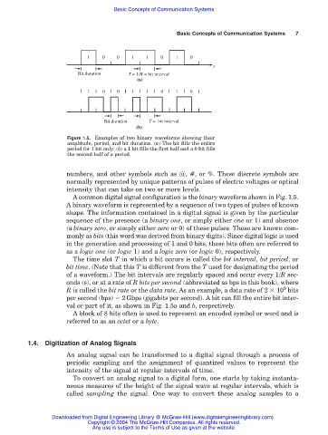
Figure 1.5. Examples of two binary waveforms showing their
amplitude, period, and bit duration. (a) The bit fills the entire
period for 1 bit only; (b) a 1 bit fills the first half and a 0 bit fills
the second half of a period.
numbers, and other symbols such as @, #, or %. These discrete symbols are
normally represented by unique patterns of pulses of electric voltages or optical
intensity that can take on two or more levels.
A common digital signal configuration is the binary waveform shown in Fig. 1.5.
A binary waveform is represented by a sequence of two types of pulses of known
shape. The information contained in a digital signal is given by the particular
sequence of the presence (a binary one, or simply either one or 1) and absence
(a binary zero, or simply either zero or 0) of these pulses. These are known com-
monly as bits (this word was derived from binary digits). Since digital logic is used
in the generation and processing of 1 and 0 bits, these bits often are referred to
as a logic one (or logic 1) and a logic zero (or logic 0), respectively.
The time slot T in which a bit occurs is called the bit interval, bit period, or
bit time. (Note that this T is different from the T used for designating the period
of a waveform.) The bit intervals are regularly spaced and occur every 1/R sec-
onds (s), or at a rate of R bits per second (abbreviated as bps in this book), where
9
R is called the bit rate or the data rate. As an example, a data rate of 2 10 bits
per second (bps) 2Gbps (gigabits per second). A bit can fill the entire bit inter-
val or part of it, as shown in Fig. 1.5a and b, respectively.
A block of 8 bits often is used to represent an encoded symbol or word and is
referred to as an octet or a byte.
1.4. Digitization of Analog Signals
An analog signal can be transformed to a digital signal through a process of
periodic sampling and the assignment of quantized values to represent the
intensity of the signal at regular intervals of time.
To convert an analog signal to a digital form, one starts by taking instanta-
neous measures of the height of the signal wave at regular intervals, which is
called sampling the signal. One way to convert these analog samples to a
Downloaded from Digital Engineering Library @ McGraw-Hill (www.digitalengineeringlibrary.com)
Copyright © 2004 The McGraw-Hill Companies. All rights reserved.
Any use is subject to the Terms of Use as given at the website.