
Page 21 - Optical Communications Essentials
P. 21
Basic Concepts of Communication Systems
Basic Concepts of Communication Systems 11
1.6. Transmission Channels
Depending on what portion of the electromagnetic spectrum is used, electro-
magnetic signals can travel through a vacuum, air, or other transmission media.
For example, electricity travels well through copper wires but not through glass.
Light, on the other hand, travels well through air, glass, and certain plastic
materials but not through copper.
1.6.1. Carrier waves
As electrical communication systems became more sophisticated, an increasingly
greater portion of the electromagnetic spectrum was utilized for conveying larger
amounts of information faster from one place to another. The reason for this
development trend is that in electrical systems the physical properties of various
transmission media are such that each medium type has a different frequency
band in which signals can be transported efficiently. To utilize this property, infor-
mation usually is transferred over the communication channel by superimposing
the data onto a sinusoidally varying electromagnetic wave, which has a frequency
response that matches the transfer properties of the medium. This wave is known
as the carrier. At the destination the information is removed from the carrier
wave and processed as desired. Since the amount of information that can be
transmitted is directly related to the frequency range over which the carrier oper-
ates, increasing the carrier frequency theoretically increases the available trans-
mission bandwidth and, consequently, provides a larger information capacity.
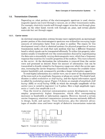
To send digital information on a carrier wave, one or more of the characteristics
of the wave such as its amplitude, frequency, or phase are varied. This kind of mod-
ification is called modulation or shift keying, and the digital information signal
is called the modulating signal. Figure 1.9 shows an example of amplitude shift
keying (ASK) or on/off keying (OOK) in which the strength (amplitude) of the
carrier wave is varied to represent 1 or 0 pulses. Here a high amplitude repre-
sents a 1 and a low amplitude is a 0.
Thus the trend in electrical communication system developments was to
employ progressively higher frequencies, which offer corresponding
increases in bandwidth or information capacity. However, beyond a certain
carrier frequency, electrical transmission systems become extremely difficult
to design, build, and operate. These limitations, plus the inherent advan-
tages of smaller sizes and lower weight of dielectric transmission materials
Figure 1.9. Concept of carrier waves.
Downloaded from Digital Engineering Library @ McGraw-Hill (www.digitalengineeringlibrary.com)
Copyright © 2004 The McGraw-Hill Companies. All rights reserved.
Any use is subject to the Terms of Use as given at the website.