
Page 18 - Optical Communications Essentials
P. 18
Basic Concepts of Communication Systems
8 Chapter One
digital format is to simply divide the amplitude excursion of the analog signal
into N equally spaced levels, designated by integers, and to assign a discrete
binary word to each of these N integer values. Each analog sample is then
assigned one of these integer values. This process is known as quantization.
Since the signal varies continuously in time, this process generates a sequence
of real numbers.
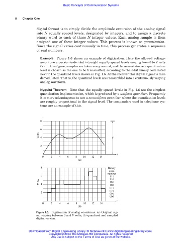
Example Figure 1.6 shows an example of digitization. Here the allowed voltage-
amplitude excursion is divided into eight equally spaced levels ranging from 0 to V volts
(V). In this figure, samples are taken every second, and the nearest discrete quantization
level is chosen as the one to be transmitted, according to the 3-bit binary code listed
next to the quantized levels shown in Fig. 1.6. At the receiver this digital signal is then
demodulated. That is, the quantized levels are reassembled into a continuously varying
analog waveform.
Nyquist Theorem Note that the equally spaced levels in Fig. 1.6 are the simplest
quantization implementation, which is produced by a uniform quantizer. Frequently
it is more advantageous to use a nonuniform quantizer where the quantization levels
are roughly proportional to the signal level. The companders used in telephone sys-
tems are an example of this.
8
6
Volts 4 V
2
t
0 2 4 6 8 10 12 14
(a)
8 Binary
code
number
6 111
Volts 4 110
101
100
011
010
2
001
000
t
0 2 4 6 8 10 12 14
(b)
Figure 1.6. Digitization of analog waveforms. (a) Original sig-
nal varying between 0 and V volts; (b) quantized and sampled
digital version.
Downloaded from Digital Engineering Library @ McGraw-Hill (www.digitalengineeringlibrary.com)
Copyright © 2004 The McGraw-Hill Companies. All rights reserved.
Any use is subject to the Terms of Use as given at the website.