
Page 166 - Optical Communications Essentials
P. 166
Passive Optical Components
156 Chapter Nine
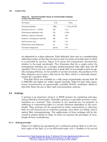
TABLE 9.5. Typical Parameter Values of Commercially Available
50-GHz Thin-Film Filters
Parameter Unit Value
Channel passband GHz 10 at 0.5dB
Insertion loss at f c 10GHz dB 3.5
Polarization-dependent loss dB 0.20
Isolation, adjacent channels dB 25
Isolation, nonadjacent channels dB 40
Optical return loss dB 45
Polarization mode dispersion ps 0.2
Chromatic dispersion ps/nm 50
are deposited on a glass substrate. Each dielectric layer acts as a nonabsorbing
reflecting surface, so that the structure is that of a series of cavities each of which
is surrounded by mirrors. Figure 9.10 shows the transmission characteristic
relative to the peak wavelength. This illustrates that for a single cavity the
transmission function has a sharply peaked passband with sides that roll off
smoothly. This is not very useful since a small shift in wavelength results in rap-
idly changing filtering. As the number of cavities increases, the passband of the
filter sharpens up to create a flat top for the filter, which is a desirable charac-
teristic for a practical filter.
Thin-film filters are available in a wide range of passbands varying from 50
to 800GHz and higher for widely spaced channels. Table 9.5 lists some opera-
tional characteristics of commercially available 50-GHz multilayer dielectric
thin-film filters for use in fiber optic communication systems.
9.4. Gratings
A grating is an important element in WDM systems for combining and sepa-
rating individual wavelengths. Basically a grating is a periodic structure or per-
turbation in a material. This variation in the material has the property of
reflecting or transmitting light in a certain direction depending on the wave-
length. Thus gratings can be categorized as either transmitting or reflecting.
Here we will concentrate on reflection gratings, since these are widely used in
optical fiber communications. The applications of these gratings will be dis-
cussed in greater detail in Chap. 12 when we examine the principles of wave-
length division multiplexing.
9.4.1. Grating principle
Figure 9.11 defines key parameters for a reflection grating. Here θ i is the inci-
dent angle of the light, θ d is the diffracted angle, and Λ (lambda) is the period
Downloaded from Digital Engineering Library @ McGraw-Hill (www.digitalengineeringlibrary.com)
Copyright © 2004 The McGraw-Hill Companies. All rights reserved.
Any use is subject to the Terms of Use as given at the website.