
Page 168 - Optical Communications Essentials
P. 168
Passive Optical Components
158 Chapter Nine
λ uv = 244 nm /2 /2 λ uv = 244 nm
Interference
Ge-doped pattern
fiber core
V
n clad
n eff V n core
L
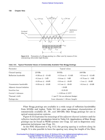
Figure 9.12. Formation of a Bragg grating in a fiber core by means of two
intersecting ultraviolet light beams.
TABLE 9.6. Typical Parameter Values of Commercially Available Fiber Bragg Gratings
Parameter Typical values
Channel spacing 25GHz 50GHz 100GHz
Reflection bandwidth 0.08nm @ 0.5dB 0.15nm @ 0.5dB 0.3nm @ 0.5dB
0.2nm @ 3dB 0.4nm @ 3dB 0.75nm @ 3dB
0.25nm @ 25dB 0.5nm @ 25dB 1nm @ 25dB
Transmission bandwidth 0.05nm @ 25dB 0.1nm @ 25dB 0.2nm @ 25dB
Adjacent channel isolation 30dB
Insertion loss 0.25dB
Central λ tolerance 0.05nm @ 25°C
Thermal λ drift 1 pm/°C (for an athermal design)
Package size 5mm (diameter) 80mm (length)
Fiber Bragg gratings are available in a wide range of reflection bandwidths
from 25GHz and higher. Table 9.6 lists some operational characteristics of
commercially available 25-, 50-, and 100-GHz fiber Bragg gratings for use in
optical communication systems.
Figure 9.13 illustrates the meanings of the adjacent channel isolation and the
reflection bandwidth parameters listed in Table 9.6. Applications of fiber Bragg
gratings can be found in WDM systems (see Chap. 12) and in dispersion com-
pensation techniques (see Chap. 15).
In the FBG illustrated in Fig. 9.12, the grating spacing is uniform along its
length. It is also possible to have the spacing vary along the length of the fiber,
Downloaded from Digital Engineering Library @ McGraw-Hill (www.digitalengineeringlibrary.com)
Copyright © 2004 The McGraw-Hill Companies. All rights reserved.
Any use is subject to the Terms of Use as given at the website.