
Page 167 - Optical Communications Essentials
P. 167
Passive Optical Components
Passive Optical Components 157
Normal to grating
Imaging plane
λ 1 +λ 2
λ 1
d
λ 2
i
Reflection grating
Grating period
V
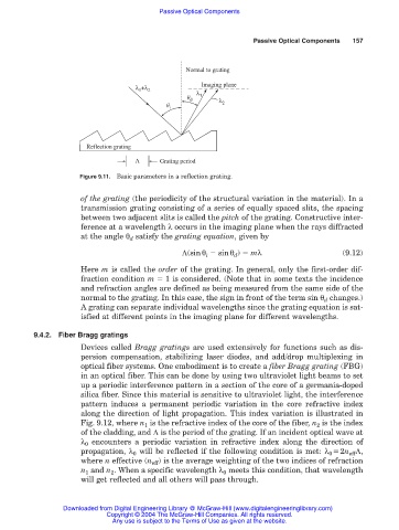
Figure 9.11. Basic parameters in a reflection grating.
of the grating (the periodicity of the structural variation in the material). In a
transmission grating consisting of a series of equally spaced slits, the spacing
between two adjacent slits is called the pitch of the grating. Constructive inter-
ference at a wavelength λ occurs in the imaging plane when the rays diffracted
at the angle θ d satisfy the grating equation, given by
Λ(sinθ i sinθ d ) mλ (9.12)
Here m is called the order of the grating. In general, only the first-order dif-
fraction condition m 1 is considered. (Note that in some texts the incidence
and refraction angles are defined as being measured from the same side of the
normal to the grating. In this case, the sign in front of the term sin θ d changes.)
A grating can separate individual wavelengths since the grating equation is sat-
isfied at different points in the imaging plane for different wavelengths.
9.4.2. Fiber Bragg gratings
Devices called Bragg gratings are used extensively for functions such as dis-
persion compensation, stabilizing laser diodes, and add/drop multiplexing in
optical fiber systems. One embodiment is to create a fiber Bragg grating (FBG)
in an optical fiber. This can be done by using two ultraviolet light beams to set
up a periodic interference pattern in a section of the core of a germania-doped
silica fiber. Since this material is sensitive to ultraviolet light, the interference
pattern induces a permanent periodic variation in the core refractive index
along the direction of light propagation. This index variation is illustrated in
Fig. 9.12, where n is the refractive index of the core of the fiber, n 2 is the index
1
of the cladding, and Λ is the period of the grating. If an incident optical wave at
λ 0 encounters a periodic variation in refractive index along the direction of
propagation, λ 0 will be reflected if the following condition is met: λ 0 2n eff Λ,
where n effective (n eff ) is the average weighting of the two indices of refraction
n 1 and n 2 . When a specific wavelength λ 0 meets this condition, that wavelength
will get reflected and all others will pass through.
Downloaded from Digital Engineering Library @ McGraw-Hill (www.digitalengineeringlibrary.com)
Copyright © 2004 The McGraw-Hill Companies. All rights reserved.
Any use is subject to the Terms of Use as given at the website.