
Page 187 - Optical Communications Essentials
P. 187
Optical Amplifiers
Optical Amplifiers 177
3. Postamplifier. Placing an amplification device immediately after the optical
transmitter gives a boost to the light level right at the beginning of a fiber
link, as the bottom schematic in Fig. 11.1 shows. This is known as a
postamplifier (called post since it comes after the transmitter) and serves to
increase the transmission distance by 10 to 100km depending on the amplifier
gain and fiber loss. As an example, using this boosting technique together
with an optical preamplifier at the receiving end can enable continuous
underwater transmission distances of 200 to 250km.
11.2. Amplification Mechanism
All optical amplifiers increase the power level of incident light through a
process of stimulated emission of radiation. Recall from Chap. 6 that stimulated
emission occurs when some external stimulant, such as a signal photon, causes
an excited electron sitting at a higher energy level to drop to the ground state.
The photon emitted in this process has the same energy (i.e., the same wave-
length) as the incident signal photon and is in phase with it. This means their
amplitudes add to produce a brighter light. For stimulated emission to occur,
there must be a population inversion of carriers, which means that there are
more electrons in an excited state than in the ground state. Since this is not a
normal condition, population inversion is achieved by supplying external
energy to boost (pump) electrons to a higher energy level.
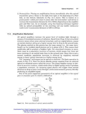
The “pumping” techniques can be optical or electrical. The basic operation is
shown in Fig. 11.2. Here the device absorbs energy supplied from an external
optical or electrical source called the pump. The pump supplies energy to elec-
trons in an active medium, which raises them to higher energy levels to produce
a population inversion. An incoming signal photon will trigger these excited
electrons to drop to lower levels through a stimulated emission process, thereby
producing an amplified signal.
One of the most important parameters of an optical amplifier is the signal
gain or amplifier gain G, which is defined as
G = P out (11.1)
P in
Figure 11.2. Basic operation of a generic optical amplifier.
Downloaded from Digital Engineering Library @ McGraw-Hill (www.digitalengineeringlibrary.com)
Copyright © 2004 The McGraw-Hill Companies. All rights reserved.
Any use is subject to the Terms of Use as given at the website.