
Page 189 - Optical Communications Essentials
P. 189
Optical Amplifiers
Optical Amplifiers 179
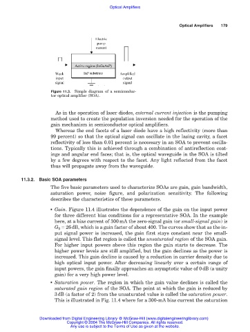
Figure 11.3. Simple diagram of a semiconduc-
tor optical amplifier (SOA).
As in the operation of laser diodes, external current injection is the pumping
method used to create the population inversion needed for the operation of the
gain mechanism in semiconductor optical amplifiers.
Whereas the end facets of a laser diode have a high reflectivity (more than
99 percent) so that the optical signal can oscillate in the lasing cavity, a facet
reflectivity of less than 0.01 percent is necessary in an SOA to prevent oscilla-
tions. Typically this is achieved through a combination of antireflection coat-
ings and angular end faces; that is, the optical waveguide in the SOA is tilted
by a few degrees with respect to the facet. Any light reflected from the facet
thus will propagate away from the waveguide.
11.3.2. Basic SOA parameters
The five basic parameters used to characterize SOAs are gain, gain bandwidth,
saturation power, noise figure, and polarization sensitivity. The following
describes the characteristics of these parameters.
■ Gain. Figure 11.4 illustrates the dependence of the gain on the input power
for three different bias conditions for a representative SOA. In the example
here, at a bias current of 300mA the zero-signal gain (or small-signal gain) is
G 0 26dB, which is a gain factor of about 400. The curves show that as the in-
put signal power is increased, the gain first stays constant near the small-
signal level. This flat region is called the unsaturated region of the SOA gain.
For higher input powers above this region the gain starts to decrease. The
higher power levels are still amplified, but the gain declines as the power is
increased. This gain decline is caused by a reduction in carrier density due to
high optical input power. After decreasing linearly over a certain range of
input powers, the gain finally approaches an asymptotic value of 0dB (a unity
gain) for a very high power level.
■ Saturation power. The region in which the gain value declines is called the
saturated gain region of the SOA. The point at which the gain is reduced by
3dB (a factor of 2) from the unsaturated value is called the saturation power.
This is illustrated in Fig. 11.4 where for a 300-mA bias current the saturation
Downloaded from Digital Engineering Library @ McGraw-Hill (www.digitalengineeringlibrary.com)
Copyright © 2004 The McGraw-Hill Companies. All rights reserved.
Any use is subject to the Terms of Use as given at the website.