
Page 200 - Optical Communications Essentials
P. 200
Optical Amplifiers
190 Chapter Eleven
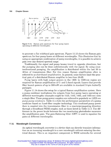
Figure 11.13. Raman gain spectrum for four pump lasers
operating at different wavelengths.
to generate a flat wideband gain spectrum. Figure 11.13 shows the Raman gain
spectrum for four pump lasers at different wavelengths. This illustrates that by
using an appropriate combination of pump wavelengths, it is possible to achieve
gain over any desired spectral range.
Traditionally the signal and pump beams travel in opposite directions, but
the pumping also can be done codirectionally with the signal. By using coun-
terdirectional pumping, the amplification is distributed within the last 20 to
40km of transmission fiber. For this reason Raman amplification often is
referred to as distributed amplification. In general, noise factors limit the prac-
tical gain of a distributed Raman amplifier to less than 20dB.
Pump lasers with high output powers in the 1400- to 1500-nm region are
required for Raman amplification of C- and L-band signals. Lasers that provide
fiber launch powers of up to 300mW are available in standard 14-pin butterfly
packages.
Figure 11.14 shows the setup for a typical Raman amplification system. Here
a pump combiner multiplexes the outputs from four pump lasers operating at
different wavelengths (examples might be 1425, 1445, 1465, and 1485nm) onto
a single fiber. These pump power couplers are referred to popularly as 14XX-nm
pump-pump combiners. Table 11.4 lists the performance parameters of a pump
combiner based on fused-fiber coupler technology. This combined pump power
then is coupled into the transmission fiber in a counterpropagating direction
through a broadband WDM coupler, such as those listed in Table 11.5. The dif-
ference in the power levels between the two monitoring photodiodes measures
the amplification gain. The gain-flattening filter (GFF) is used to equalize the
gains at different wavelengths.
11.6. Wavelength Conversion
An optical wavelength converter is a device that can directly translate informa-
tion on an incoming wavelength to a new wavelength without entering the elec-
trical domain. This is an important component in WDM networks for several
Downloaded from Digital Engineering Library @ McGraw-Hill (www.digitalengineeringlibrary.com)
Copyright © 2004 The McGraw-Hill Companies. All rights reserved.
Any use is subject to the Terms of Use as given at the website.