
Page 196 - Optical Communications Essentials
P. 196
Optical Amplifiers
186 Chapter Eleven
TABLE 11.2. Comparison of EDFA Pump Lasers
Parameter 980-nm laser 1480-nm laser
Minimum noise figure 4dB 5.5dB
Fiber-coupled power ● 300mW (standard) ● 250mW (standard)
● 500mW (high-power) ● 310mW (high-power)
Spectral width 5nm @ 250mW 8nm @ 250mW
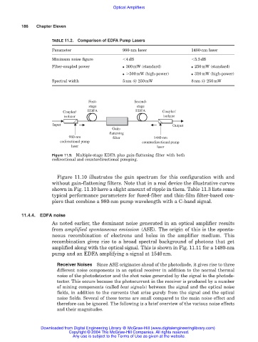
First- Second-
stage stage
Coupler/ EDFA EDFA Coupler/
isolator isolator
Input Output
Gain-
flattening
980-nm filter 1480-nm
codirectional pump counterdirectional pump
laser laser
Figure 11.9. Multiple-stage EDFA plus gain-flattening filter with both
codirectional and counterdirectional pumping.
Figure 11.10 illustrates the gain spectrum for this configuration with and
without gain-flattening filters. Note that in a real device the illustrative curves
shown in Fig. 11.10 have a slight amount of ripple in them. Table 11.3 lists some
typical performance parameters for fused-fiber and thin-film filter-based cou-
plers that combine a 980-nm pump wavelength with a C-band signal.
11.4.4. EDFA noise
As noted earlier, the dominant noise generated in an optical amplifier results
from amplified spontaneous emission (ASE). The origin of this is the sponta-
neous recombination of electrons and holes in the amplifier medium. This
recombination gives rise to a broad spectral background of photons that get
amplified along with the optical signal. This is shown in Fig. 11.11 for a 1480-nm
pump and an EDFA amplifying a signal at 1540nm.
Receiver Noises Since ASE originates ahead of the photodiode, it gives rise to three
different noise components in an optical receiver in addition to the normal thermal
noise of the photodetector and the shot noise generated by the signal in the photode-
tector. This occurs because the photocurrent in the receiver is produced by a number
of mixing components (called beat signals) between the signal and the optical noise
fields, in addition to the currents that arise purely from the signal and the optical
noise fields. Several of these terms are small compared to the main noise effect and
therefore can be ignored. The following is a brief overview of the various noise effects
and their magnitudes.
Downloaded from Digital Engineering Library @ McGraw-Hill (www.digitalengineeringlibrary.com)
Copyright © 2004 The McGraw-Hill Companies. All rights reserved.
Any use is subject to the Terms of Use as given at the website.