
Page 197 - Optical Communications Essentials
P. 197
Optical Amplifiers
Optical Amplifiers 187
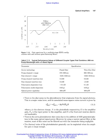
Figure 11.10. Gain spectrum for a multiple-stage EDFA config-
uration with and without gain-flattening filters.
TABLE 11.3. Typical Performance Values of Different Coupler Types That Combine a 980-nm
Pump Wavelength with a C-Band Signal
Parameter Specification
Device technology Fused fiber Thin-film filter
Pump channel λ range 970–990nm 965–995nm
Pass channel λ range 1535–1565nm 1520–1610nm
Pump channel insertion loss 0.2dB 0.6dB
Pass channel insertion loss 0.2dB 1.0dB
Polarization-dependent loss 0.1dB 0.1dB
Polarization mode dispersion 0.05ps 0.05ps
Optical power capability 500mW 500mW
■ There is the shot noise in the photodetector that originates from the signal photons.
This is a major noise term, and its associated mean-square noise current is given by
i 2 shot σ 2 shot -s 2qGP in B (11.3)
R
where q is the electron charge, R is the photodiode responsivity, G is the amplifier
gain, P in is the input power to the amplifier, and B is the front-end receiver electri-
cal bandwidth.
■ There is the extra photodetector shot noise due to the addition of ASE-generated pho-
tons to the mean optical signal power. However, by using a narrow optical filter at the
receiver, most of this noise can be filtered out with the remainder being negligible.
■ The thermal noise of the photodetector generally can be neglected when the ampli-
fier gain is large enough.
Downloaded from Digital Engineering Library @ McGraw-Hill (www.digitalengineeringlibrary.com)
Copyright © 2004 The McGraw-Hill Companies. All rights reserved.
Any use is subject to the Terms of Use as given at the website.