
Page 223 - Optical Communications Essentials
P. 223
Wavelength Division Multiplexing
Wavelength Division Multiplexing 213
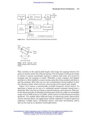
Light
throughput
Laser diode Laser Modulator Tap
Tap
Laser
Laser diode
driver diode Modulator coupler
driver
diode
coupler
Etalon
photodiode
Etalon Beam splitter
Beam splitter
Micro-
processor
Reference
photodiode Wavelength locker assembly
Figure 12.12. Top-level function of a wavelength locker assembly.
Laser
input Etalon
d'
Etalon
output
d < d'
Optical path length
Figure 12.13. Optical path
length change when tilting an
etalon.
This variation in the optical path length will change the spacing between the
peaks to exactly match the channel spacing. The technique of tilting the etalon
to achieve a precise wavelength spacing is tedious and costly and cannot be
changed once the package is sealed. Therefore a more common and simpler
method is to first establish a coarse tuning using the tilting method and then to
seal the package. After this one can use a temperature-tuning method to alter
the refractive index, which induces a fine-tuning of the optical path length.
Figure 12.14 shows a commercially available frequency control device. Its
operation is based on the use of a calibrated optical resonator locked onto a
molecular filter, thereby providing an optical frequency grid reference. This par-
ticular device provides an absolute multifrequency grid over a 200-nm wavelength
range with an FSR as low as 12.5GHz, which covers the full telecommunication
spectrum. The module offers different types of referencing peaks enhanced by
various internal filters. Its applications include calibration of optical spectrum
analyzers, tunable lasers, wavelength meters, and other instruments, and it
also can be used as an absolute wavelength locker.
Downloaded from Digital Engineering Library @ McGraw-Hill (www.digitalengineeringlibrary.com)
Copyright © 2004 The McGraw-Hill Companies. All rights reserved.
Any use is subject to the Terms of Use as given at the website.