
Page 222 - Optical Communications Essentials
P. 222
Wavelength Division Multiplexing
212 Chapter Twelve
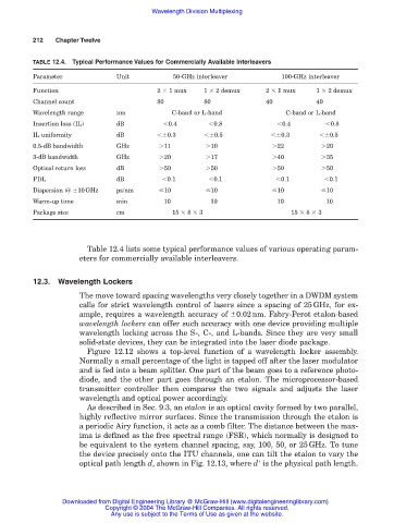
TABLE 12.4. Typical Performance Values for Commercially Available Interleavers
Parameter Unit 50-GHz interleaver 100-GHz interleaver
Function 2 1 mux 1 2 demux 2 1 mux 1 2 demux
Channel count 80 80 40 40
Wavelength range nm C-band or L-band C-band or L-band
Insertion loss (IL) dB 0.4 0.8 0.4 0.8
IL uniformity dB 0.3 0.5 0.3 0.5
0.5-dB bandwidth GHz 11 10 22 20
3-dB bandwidth GHz 20 17 40 35
Optical return loss dB 50 50 50 50
PDL dB 0.1 0.1 0.1 0.1
Dispersion @ 10GHz ps/nm 10 10 10 10
Warm-up time min 10 10 10 10
Package size cm 15 8 3 15 8 3
Table 12.4 lists some typical performance values of various operating param-
eters for commercially available interleavers.
12.3. Wavelength Lockers
The move toward spacing wavelengths very closely together in a DWDM system
calls for strict wavelength control of lasers since a spacing of 25GHz, for ex-
ample, requires a wavelength accuracy of 0.02nm. Fabry-Perot etalon-based
wavelength lockers can offer such accuracy with one device providing multiple
wavelength locking across the S-, C-, and L-bands. Since they are very small
solid-state devices, they can be integrated into the laser diode package.
Figure 12.12 shows a top-level function of a wavelength locker assembly.
Normally a small percentage of the light is tapped off after the laser modulator
and is fed into a beam splitter. One part of the beam goes to a reference photo-
diode, and the other part goes through an etalon. The microprocessor-based
transmitter controller then compares the two signals and adjusts the laser
wavelength and optical power accordingly.
As described in Sec. 9.3, an etalon is an optical cavity formed by two parallel,
highly reflective mirror surfaces. Since the transmission through the etalon is
a periodic Airy function, it acts as a comb filter. The distance between the max-
ima is defined as the free spectral range (FSR), which normally is designed to
be equivalent to the system channel spacing, say, 100, 50, or 25GHz. To tune
the device precisely onto the ITU channels, one can tilt the etalon to vary the
optical path length d, shown in Fig. 12.13, where d
is the physical path length.
Downloaded from Digital Engineering Library @ McGraw-Hill (www.digitalengineeringlibrary.com)
Copyright © 2004 The McGraw-Hill Companies. All rights reserved.
Any use is subject to the Terms of Use as given at the website.