
Page 219 - Optical Communications Essentials
P. 219
Wavelength Division Multiplexing
Wavelength Division Multiplexing 209
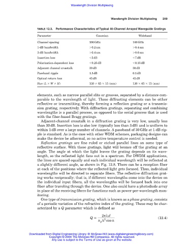
TABLE 12.3. Performance Characteristics of Typical 40-Channel Arrayed Waveguide Gratings
Parameter Gaussian Wideband
Channel spacing 100GHz 100GHz
1-dB bandwidth 0.2nm 0.4nm
3-dB bandwidth 0.4nm 0.6nm
Insertion loss 5dB 7dB
Polarization-dependent loss 0.25dB 0.15dB
Adjacent channel crosstalk 30dB 30dB
Passband ripple 1.5dB 0.5dB
Optical return loss 45dB 45dB
Size (L W H) 130 65 15 (mm) 130 65 15 (mm)
elements, such as narrow parallel slits or grooves, separated by a distance com-
parable to the wavelength of light. These diffracting elements can be either
reflective or transmitting, thereby forming a reflection grating or a transmis-
sion grating, respectively. With diffraction gratings, separating and combining
wavelengths is a parallel process, as opposed to the serial process that is used
with the fiber-based Bragg gratings.
Adjacent-channel crosstalk in a diffraction grating is very low, usually less
than 30dB. Insertion loss is also low (typically less than 3dB) and is uniform to
within 1dB over a large number of channels. A passband of 30GHz at 1-dB rip-
ple is standard. As is the case with other WDM schemes, packaging designs can
make the device be athermal, so no active temperature control is needed.
Reflection gratings are fine ruled or etched parallel lines on some type of
reflective surface. With these gratings, light will bounce off the grating at an
angle. The angle at which the light leaves the grating depends on its wave-
length, so the reflected light fans out in a spectrum. For DWDM applications,
the lines are spaced equally and each individual wavelength will be reflected at
a slightly different angle, as shown in Fig. 12.8. There can be a reception fiber
at each of the positions where the reflected light gets focused. Thus, individual
wavelengths will be directed to separate fibers. The reflective diffraction grat-
ing works reciprocally; that is, if different wavelengths come into the device on
the individual input fibers, all the wavelengths will be focused back into one
fiber after traveling through the device. One also could have a photodiode array
in place of the receiving fibers for functions such as power-per-wavelength mon-
itoring.
One type of transmission grating, which is known as a phase grating, consists
of a periodic variation of the refractive index of the grating. These may be char-
acterized by a Q parameter which is defined as
2πλd
Q (12.4)
n g Λ cosα
2
Downloaded from Digital Engineering Library @ McGraw-Hill (www.digitalengineeringlibrary.com)
Copyright © 2004 The McGraw-Hill Companies. All rights reserved.
Any use is subject to the Terms of Use as given at the website.