
Page 216 - Optical Communications Essentials
P. 216
Wavelength Division Multiplexing
206 Chapter Twelve
Similar to the use of thin-film filters to form multiplexers, the size limita-
tion when using fiber Bragg gratings is that one filter is needed for each wave-
length and normally the operation is sequential with wavelengths being trans-
mitted by one filter after another. Therefore the losses are not uniform from
channel to channel, since each wavelength goes through a different number of
circulators and fiber gratings, each of which adds loss to that channel. This
may be acceptable for a small number of channels, but the loss differential
between the first and last inserted wavelengths is a restriction for large chan-
nel counts.
12.2.3. Arrayed waveguide gratings
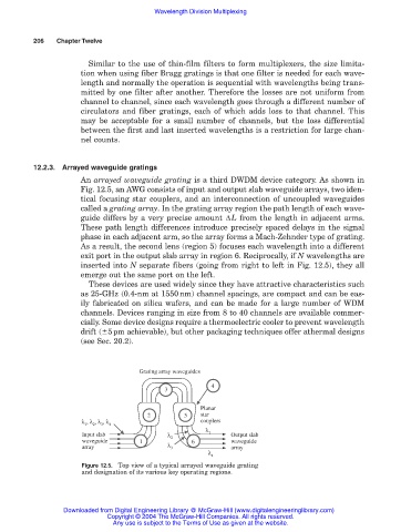
An arrayed waveguide grating is a third DWDM device category. As shown in
Fig. 12.5, an AWG consists of input and output slab waveguide arrays, two iden-
tical focusing star couplers, and an interconnection of uncoupled waveguides
called a grating array. In the grating array region the path length of each wave-
guide differs by a very precise amount ∆L from the length in adjacent arms.
These path length differences introduce precisely spaced delays in the signal
phase in each adjacent arm, so the array forms a Mach-Zehnder type of grating.
As a result, the second lens (region 5) focuses each wavelength into a different
exit port in the output slab array in region 6. Reciprocally, if N wavelengths are
inserted into N separate fibers (going from right to left in Fig. 12.5), they all
emerge out the same port on the left.
These devices are used widely since they have attractive characteristics such
as 25-GHz (0.4-nm at 1550nm) channel spacings, are compact and can be eas-
ily fabricated on silica wafers, and can be made for a large number of WDM
channels. Devices ranging in size from 8 to 40 channels are available commer-
cially. Some device designs require a thermoelectric cooler to prevent wavelength
drift ( 5pm achievable), but other packaging techniques offer athermal designs
(see Sec. 20.2).
Grating array waveguides
4
3
Planar
2 5 star
λ , λ , λ , λ 4 couplers
3
2
1
λ
Input slab λ 2 1 Output slab
waveguide 1 6 waveguide
array λ 3 array
λ 4
Figure 12.5. Top view of a typical arrayed waveguide grating
and designation of its various key operating regions.
Downloaded from Digital Engineering Library @ McGraw-Hill (www.digitalengineeringlibrary.com)
Copyright © 2004 The McGraw-Hill Companies. All rights reserved.
Any use is subject to the Terms of Use as given at the website.