
Page 214 - Optical Communications Essentials
P. 214
Wavelength Division Multiplexing
204 Chapter Twelve
TFF 2
λ 1
λ 2
λ 1 , λ 2
λ 3
λ 1 , λ 2 , λ 3
λ 4
TFF 3 TFF 4
λ 1 , λ 2 , λ 3 , λ 4
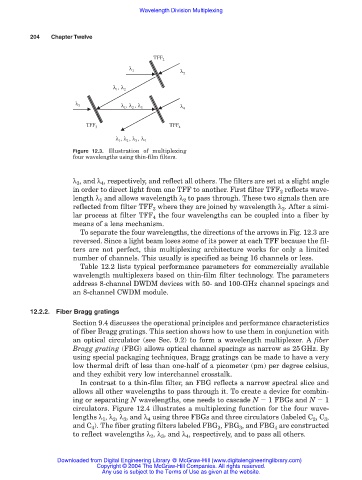
Figure 12.3. Illustration of multiplexing
four wavelengths using thin-film filters.
λ 3 , and λ 4 , respectively, and reflect all others. The filters are set at a slight angle
in order to direct light from one TFF to another. First filter TFF 2 reflects wave-
length λ 1 and allows wavelength λ 2 to pass through. These two signals then are
reflected from filter TFF 3 where they are joined by wavelength λ 3 . After a simi-
lar process at filter TFF 4 the four wavelengths can be coupled into a fiber by
means of a lens mechanism.
To separate the four wavelengths, the directions of the arrows in Fig. 12.3 are
reversed. Since a light beam loses some of its power at each TFF because the fil-
ters are not perfect, this multiplexing architecture works for only a limited
number of channels. This usually is specified as being 16 channels or less.
Table 12.2 lists typical performance parameters for commercially available
wavelength multiplexers based on thin-film filter technology. The parameters
address 8-channel DWDM devices with 50- and 100-GHz channel spacings and
an 8-channel CWDM module.
12.2.2. Fiber Bragg gratings
Section 9.4 discusses the operational principles and performance characteristics
of fiber Bragg gratings. This section shows how to use them in conjunction with
an optical circulator (see Sec. 9.2) to form a wavelength multiplexer. A fiber
Bragg grating (FBG) allows optical channel spacings as narrow as 25GHz. By
using special packaging techniques, Bragg gratings can be made to have a very
low thermal drift of less than one-half of a picometer (pm) per degree celsius,
and they exhibit very low interchannel crosstalk.
In contrast to a thin-film filter, an FBG reflects a narrow spectral slice and
allows all other wavelengths to pass through it. To create a device for combin-
ing or separating N wavelengths, one needs to cascade N 1 FBGs and N 1
circulators. Figure 12.4 illustrates a multiplexing function for the four wave-
lengths λ 1 , λ 2 , λ 3 , and λ 4 using three FBGs and three circulators (labeled C 2 , C 3 ,
and C 4 ). The fiber grating filters labeled FBG 2 , FBG 3 , and FBG 4 are constructed
to reflect wavelengths λ 2 , λ 3 , and λ 4 , respectively, and to pass all others.
Downloaded from Digital Engineering Library @ McGraw-Hill (www.digitalengineeringlibrary.com)
Copyright © 2004 The McGraw-Hill Companies. All rights reserved.
Any use is subject to the Terms of Use as given at the website.