
Page 212 - Optical Communications Essentials
P. 212
Wavelength Division Multiplexing
202 Chapter Twelve
12.1.3. Generic WDM link
The implementation of WDM networks requires a variety of passive and/or
active devices to combine, distribute, isolate, add, drop, attenuate, and amplify
optical power at different wavelengths. Passive devices require no external con-
trol for their operation, so they have a fixed application in WDM networks.
These passive components are used to split and combine or tap off optical sig-
nals. The performance of active devices can be controlled electronically, thereby
providing a large degree of network flexibility. Active WDM components include
tunable optical filters, tunable sources, add/drop multiplexers, VOAs, DGEs,
optical switches, and optical amplifiers.
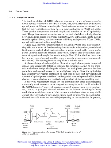
Figure 12.2 shows the implementation of a simple WDM link. The transmit-
ting side has a series of fixed-wavelength or tunable independently modulated
light sources, each of which emits signals at a unique wavelength. Here a multi-
plexer (mux) is needed to combine these optical outputs into a continuous spec-
trum of signals and couple them onto a single fiber. Within the link there may
be various types of optical amplifiers and a variety of specialized components
(not shown). The spacing between amplifiers is called a span.
At the receiving end a demultiplexer (demux) is required to separate the optical
signals into appropriate detection channels for signal processing. At the trans-
mitter the basic design challenge is to have the multiplexer provide a low-loss
path from each optical source to the multiplexer output. Since the optical sig-
nals generally are tightly controlled so that they do not emit any significant
amount of optical power outside of the designated channel spectral width, inter-
channel crosstalk factors are relatively unimportant at the transmitting end.
A different requirement exists for the demultiplexer, since photodetectors
are usually sensitive over a broad range of wavelengths, which could include all
the WDM channels. To prevent spurious signals from entering a receiving chan-
nel, that is, to give good channel isolation of the different wavelengths being
used, the demultiplexer must exhibit narrow spectral operation, or very stable
optical filters with sharp wavelength cutoffs must be used. The tolerable inter-
channel crosstalk levels can vary widely depending on the application. In general,
WDM WDM Optical
mux Optical fiber demux receivers
λ 1 λ 1
• •
• •
λ N λ N
Postamplifier In-line Preamplifier
Fixed or amplifier Optical
tunable filters
Span
sources
Figure 12.2. Implementation of a simple WDM link showing the use of
different amplifiers.
Downloaded from Digital Engineering Library @ McGraw-Hill (www.digitalengineeringlibrary.com)
Copyright © 2004 The McGraw-Hill Companies. All rights reserved.
Any use is subject to the Terms of Use as given at the website.