
Page 217 - Optical Communications Essentials
P. 217
Wavelength Division Multiplexing
Wavelength Division Multiplexing 207
AWG Operation The AWG shown in Fig. 12.5 works as follows:
■ Starting from the left, the input slab waveguides in region 1 are connected to the
planar star coupler (region 2) which acts as a lens.
■ The lens distributes the entering optical power among the different waveguides in
the grating array in region 3.
■ Adjacent waveguides of the grating array in region 3 differ in path length by a pre-
cise length ∆L. The path length differences ∆L can be chosen such that all input
wavelengths emerge at point 4 with different phase delays
∆L
∆Φ 2πn eff (12.2)
λ c
Here n eff is the effective refractive index of the waveguides, and λ c is the center
wavelength.
■ The second lens in region 5 refocuses the light from all the grating array waveguides
onto the output slab waveguide array in region 6.
■ Thus each wavelength is focused into a different output waveguide in region 6.
Note that the demultiplexing function of the AWG is periodic. Thus an import-
ant property of the AWG is the free spectral range (FSR), which also is known
as the demultiplexer periodicity. This periodicity is due to the fact that con-
structive interference at the output star coupler can occur for a number of
wavelengths. Basically the FSR specifies the extent of a spectral width that will
be separated across the output waveguides. The next chunk of higher or lower
spectral width having an equal width will be separated across the same output
waveguides.
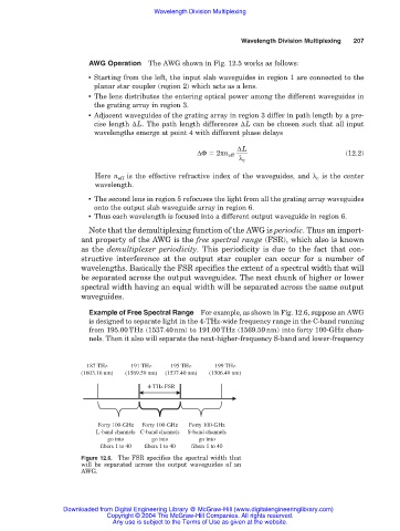
Example of Free Spectral Range For example, as shown in Fig. 12.6, suppose an AWG
is designed to separate light in the 4-THz-wide frequency range in the C-band running
from 195.00THz (1537.40nm) to 191.00THz (1569.59nm) into forty 100-GHz chan-
nels. Then it also will separate the next-higher-frequency S-band and lower-frequency
187 THz 191 THz 195 THz 199 THz
(1603.16 nm) (1569.59 nm) (1537.40 nm) (1506.49 nm)
4-THz FSR
Forty 100-GHz Forty 100-GHz Forty 100-GHz
L-band channels C-band channels S-band channels
go into go into go into
fibers 1 to 40 fibers 1 to 40 fibers 1 to 40
Figure 12.6. The FSR specifies the spectral width that
will be separated across the output waveguides of an
AWG.
Downloaded from Digital Engineering Library @ McGraw-Hill (www.digitalengineeringlibrary.com)
Copyright © 2004 The McGraw-Hill Companies. All rights reserved.
Any use is subject to the Terms of Use as given at the website.