
Page 218 - Optical Communications Essentials
P. 218
Wavelength Division Multiplexing
208 Chapter Twelve
L-band 4-THz-wide spectral chunks into the same 40 output fibers. The free spectral
range ∆λ FSR is determined from the relationship
2
λ c
FSR ∆λ FSR (12.3)
∆Ln eff
For example, for the 4-THz frequency range denoted here, the center wavelength λ c is
1550.5nm, the free spectral range ∆λ FSR should be at least 32.2nm in order to separate
all the wavelengths into distinct fibers, and the effective refractive index n eff is nomin-
ally 1.45 in silica. Then the length difference between adjacent array waveguides is
∆L 51.49µm.
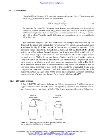
The passband shape of the AWG filter versus wavelength can be altered by the
design of the input and output slab waveguides. Two common passband shapes
are shown in Fig. 12.7. On the left is the normal or gaussian passband. This
passband shape exhibits the lowest loss at the peak, but the fact that it rolls off
quickly on either side of the peak means that it requires a high stabilization of
the laser wavelength. Furthermore, for applications where the light passes
through several AWGs, the accumulative effect of the filtering function reduces
the passband to an extremely small value. An alternative to the gaussian pass-
band shape is the flattop or wideband shape, as shown on the right in Fig. 12.7.
This wideband device has a uniform insertion loss across the passband and is
therefore not as sensitive to laser drift or the sensitivity of cascaded filters as is
the gaussian passband. However, the loss in a flattop device is usually 2 to 3dB
higher than that in a gaussian AWG. Table 12.3 compares the main operating
characteristics of these two designs for a typical 40-channel AWG.
12.2.4. Diffraction gratings
A fourth DWDM technology is based on diffraction gratings. A diffraction grat-
ing is a conventional optical device that spatially separates the different wave-
lengths contained in a beam of light. The device consists of a set of diffracting
Normal or Flattop or
Gaussian AWG wideband AWG
Rolloff
Insertion loss Passband Insertion loss Passband
Wavelength Wavelength
Figure 12.7. Two common optical-filter passband shapes: nor-
mal or gaussian and flattop or wideband.
Downloaded from Digital Engineering Library @ McGraw-Hill (www.digitalengineeringlibrary.com)
Copyright © 2004 The McGraw-Hill Companies. All rights reserved.
Any use is subject to the Terms of Use as given at the website.