
Page 215 - Optical Communications Essentials
P. 215
Wavelength Division Multiplexing
Wavelength Division Multiplexing 205
TABLE 12.2. Typical Performance Parameters for 8-Channel DWDM and CWDM Multiplexers Based
on Thin-Film-Filter Technology
Parameter 50-GHz DWDM 100-GHz DWDM 20-nm CWDM
Center wavelength accuracy 0.1nm 0.1nm 0.3nm
Channel passband @ 0.5-dB bandwidth 0.20nm 0.11nm 6.5nm
Insertion loss 4.0dB 4.0dB 4.5dB
Ripple in passband 0.5dB 0.5dB 0.5dB
Adjacent channel isolation 23dB 20dB 15dB
Directivity 50dB 55dB 50dB
Optical return loss 40dB 50dB 45dB
Polarization-dependent loss 0.1dB 0.1dB 0.1dB
Thermal wavelength drift 0.001nm/°C 0.001nm/°C 0.003nm/°C
Optical power capability 500mW 500mW 500mW
FBG 2
1 2
λ 2 λ 1
C 2
3
λ 1 , λ 2 λ 2
Circulator
ports
FBG 3
λ 1 , λ 2 , λ 3
FBG 4
λ 1 , λ 2 , λ 3 , λ 4
C 3 C 4
λ 3 λ 4
λ 3 λ 4
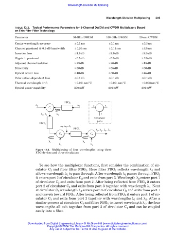
Figure 12.4. Multiplexing of four wavelengths using three
FBG devices and three circulators.
To see how the multiplexer functions, first consider the combination of cir-
culator C 2 and fiber filter FBG 2 . Here filter FBG 2 reflects wavelength λ 2 and
allows wavelength λ 1 to pass through. After wavelength λ 1 passes through FBG 2
it enters port 2 of circulator C 2 and exits from port 3. Wavelength λ 2 enters port 1
of circulator C 2 and exits from port 2. After being reflected from FBG 2 it enters
port 2 of circulator C 2 and exits from port 3 together with wavelength λ 1 . Next
at circulator C 3 wavelength λ 3 enters port 3 of circulator C 3 and exits from port 1
and travels toward FBG 3 . After being reflected from FBG 3 it enters port 1 of cir-
culator C 3 and exits from port 2 together with wavelengths λ 1 and λ 2 . After a
similar process at circulator C 4 and filter FBG 4 to insert wavelength λ 4 , the four
wavelengths all exit together from port 2 of circulator C 4 and can be coupled
easily into a fiber.
Downloaded from Digital Engineering Library @ McGraw-Hill (www.digitalengineeringlibrary.com)
Copyright © 2004 The McGraw-Hill Companies. All rights reserved.
Any use is subject to the Terms of Use as given at the website.