
Page 353 - Optical Communications Essentials
P. 353
Manufacturing Issues
Manufacturing Issues 343
cleaning, and optical-surface inspection of various types of fiber optic connect-
ors and cable assemblies. These include the SC, FC, ST, LC, MU, MT-RJ, and
MPO connectors described in Chap. 8. Connector properties, such as surface
quality, end-face curvature, fiber height, and apex offset, can be controlled
through a servo-control polishing head. The system includes an integrated
microscope and CCD camera for image capture and the manual or automatic
inspection of optical surfaces for scratches, pits, and material defects. The areas
to be examined may be defined by regions in the core, cladding, or ferrule.
Imaging software enables automatic surface-defect recognition, and a pass/fail
sorting criterion can be set. The images can be seen on a display screen that is
connected to the equipment. The machine allows a throughput of 100 to 300
connectors per hour, depending on the connector style.
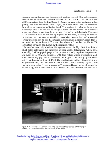
As another example, consider the system shown in Fig. 20.8 from kSaria
which fully automates the processes of fiber pigtail fabrication. When done
manually, the fiber pigtail preparation process normally requires five processes
and takes up to 10min to complete. With this system a fiber preparation mod-
ule automatically pays out a predetermined length of fiber (ranging from 0.75
to 3m) and prepares the end. First, the spooling/pay-out tool dispenses a pre-
programmed length of fiber, coils it, and inserts it into a holding tray with the
two ends secured for further processing. The spooled trays then are transported
to the strip, clean, and cleave tools. When the fiber preparation process is
Figure 20.8. Example of a system that fully automates the processes of fiber pigtail
fabrication. (Photo courtesy of kSaria; www.ksaria.com.)
Downloaded from Digital Engineering Library @ McGraw-Hill (www.digitalengineeringlibrary.com)
Copyright © 2004 The McGraw-Hill Companies. All rights reserved.
Any use is subject to the Terms of Use as given at the website.