
Page 348 - Optical Communications Essentials
P. 348
Manufacturing Issues
338 Chapter Twenty
Sintered glass SiO 2 powder (soot)
Reactant
gases Exhaust
Fused silica tube
Moving torch
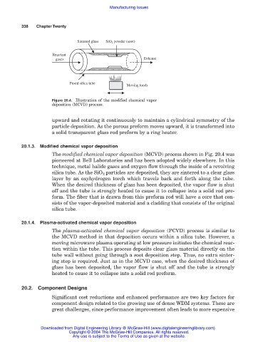
Figure 20.4. Illustration of the modified chemical vapor
deposition (MCVD) process.
upward and rotating it continuously to maintain a cylindrical symmetry of the
particle deposition. As the porous preform moves upward, it is transformed into
a solid transparent glass rod preform by a ring heater.
20.1.3. Modified chemical vapor deposition
The modified chemical vapor deposition (MCVD) process shown in Fig. 20.4 was
pioneered at Bell Laboratories and has been adopted widely elsewhere. In this
technique, metal halide gases and oxygen flow through the inside of a revolving
silica tube. As the SiO 2 particles are deposited, they are sintered to a clear glass
layer by an oxyhydrogen torch which travels back and forth along the tube.
When the desired thickness of glass has been deposited, the vapor flow is shut
off and the tube is strongly heated to cause it to collapse into a solid rod pre-
form. The fiber that is drawn from this preform rod will have a core that con-
sists of the vapor-deposited material and a cladding that consists of the original
silica tube.
20.1.4. Plasma-activated chemical vapor deposition
The plasma-activated chemical vapor deposition (PCVD) process is similar to
the MCVD method in that deposition occurs within a silica tube. However, a
moving microwave plasma operating at low pressure initiates the chemical reac-
tion within the tube. This process deposits clear glass material directly on the
tube wall without going through a soot deposition step. Thus, no extra sinter-
ing step is required. Just as in the MCVD case, when the desired thickness of
glass has been deposited, the vapor flow is shut off and the tube is strongly
heated to cause it to collapse into a solid rod preform.
20.2. Component Designs
Significant cost reductions and enhanced performance are two key factors for
component design related to the growing use of dense WDM systems. These are
great challenges, since performance improvement often leads to more expensive
Downloaded from Digital Engineering Library @ McGraw-Hill (www.digitalengineeringlibrary.com)
Copyright © 2004 The McGraw-Hill Companies. All rights reserved.
Any use is subject to the Terms of Use as given at the website.