
Page 343 - Optical Communications Essentials
P. 343
Test and Measurement
Test and Measurement 333
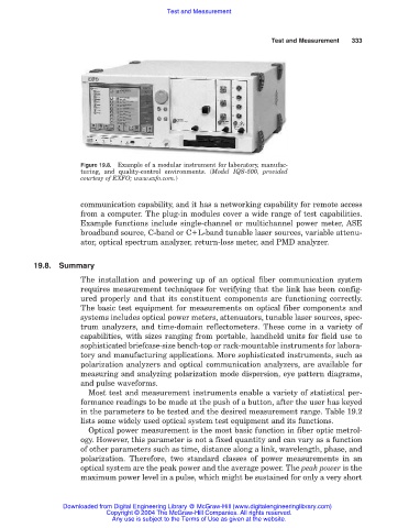
Figure 19.8. Example of a modular instrument for laboratory, manufac-
turing, and quality-control environments. (Model IQS-500, provided
courtesy of EXFO; www.exfo.com.)
communication capability, and it has a networking capability for remote access
from a computer. The plug-in modules cover a wide range of test capabilities.
Example functions include single-channel or multichannel power meter, ASE
broadband source, C-band or C L-band tunable laser sources, variable attenu-
ator, optical spectrum analyzer, return-loss meter, and PMD analyzer.
19.8. Summary
The installation and powering up of an optical fiber communication system
requires measurement techniques for verifying that the link has been config-
ured properly and that its constituent components are functioning correctly.
The basic test equipment for measurements on optical fiber components and
systems includes optical power meters, attenuators, tunable laser sources, spec-
trum analyzers, and time-domain reflectometers. These come in a variety of
capabilities, with sizes ranging from portable, handheld units for field use to
sophisticated briefcase-size bench-top or rack-mountable instruments for labora-
tory and manufacturing applications. More sophisticated instruments, such as
polarization analyzers and optical communication analyzers, are available for
measuring and analyzing polarization mode dispersion, eye pattern diagrams,
and pulse waveforms.
Most test and measurement instruments enable a variety of statistical per-
formance readings to be made at the push of a button, after the user has keyed
in the parameters to be tested and the desired measurement range. Table 19.2
lists some widely used optical system test equipment and its functions.
Optical power measurement is the most basic function in fiber optic metrol-
ogy. However, this parameter is not a fixed quantity and can vary as a function
of other parameters such as time, distance along a link, wavelength, phase, and
polarization. Therefore, two standard classes of power measurements in an
optical system are the peak power and the average power. The peak power is the
maximum power level in a pulse, which might be sustained for only a very short
Downloaded from Digital Engineering Library @ McGraw-Hill (www.digitalengineeringlibrary.com)
Copyright © 2004 The McGraw-Hill Companies. All rights reserved.
Any use is subject to the Terms of Use as given at the website.