
Page 346 - Optical Communications Essentials
P. 346
Manufacturing Issues
336 Chapter Twenty
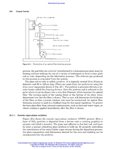
Figure 20.1. Illustration of an optical fiber-drawing process.
process, the particles are sintered (transformed to a homogeneous glass mass by
heating without melting) by one of a variety of techniques to form a clear glass
rod or tube (depending on the fabrication process). The chlorine gas produced
in this process is evacuated from the system.
The glass rod or tube is called a preform. It is typically around 10 to 25mm in
diameter and 60 to 120cm long. Fibers are made from the preform by using the
draw tower equipment shown in Fig. 20.1. The preform is precision-fed into a cir-
cular heater called the drawing furnace. Here the preform end is softened to the
point where it can be drawn into a very thin filament, which becomes the optical
fiber. The turning speed of the takeup drum at the bottom of the draw tower
determines how fast the fiber is drawn. This in turn will determine the thickness
of the fiber, so that a precise rotation rate must be maintained. An optical fiber
thickness monitor is used in a feedback loop for this speed regulation. To protect
the bare glass fiber from external contaminants, such as dust and water vapor, an
elastic coating is applied immediately after the fiber is drawn.
20.1.1. Outside vapor-phase oxidation
Figure 20.2 shows the outside vapor-phase oxidation (OVPO) process. Here a
layer of SiO 2 particles is deposited from a burner onto a rotating graphite or
ceramic rod called a mandrel. The glass soot adheres to this bait rod, and layer
by layer, a porous cylindrical glass preform is built up. By properly controlling
the constituents of the metal halide vapor stream during the deposition process,
the glass composition and dimensions desired for the core and cladding can be
incorporated into the preform.
Downloaded from Digital Engineering Library @ McGraw-Hill (www.digitalengineeringlibrary.com)
Copyright © 2004 The McGraw-Hill Companies. All rights reserved.
Any use is subject to the Terms of Use as given at the website.