
Page 341 - Optical Communications Essentials
P. 341
Test and Measurement
Test and Measurement 331
An OTDR is fundamentally an optical radar. It operates by periodically
launching narrow laser pulses into one end of a fiber under test by using either
a directional coupler or a beam splitter. The properties of the optical fiber link
then are determined by analyzing the amplitude and temporal characteristics of
the waveform of the backscattered light.
19.6.1. OTDR trace
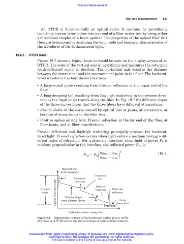
Figure 19.7 shows a typical trace as would be seen on the display screen of an
OTDR. The scale of the vertical axis is logarithmic and measures the returning
(back-reflected) signal in decibels. The horizontal axis denotes the distance
between the instrument and the measurement point in the fiber. The backscat-
tered waveform has four distinct features:
■ A large initial pulse resulting from Fresnel reflection at the input end of the
fiber.
■ A long decaying tail resulting from Rayleigh scattering in the reverse direc-
tion as the input pulse travels along the fiber. In Fig. 19.7 the different slopes
of the three curves mean that the three fibers have different attenuations.
■ Abrupt shifts in the curve caused by optical loss at joints, at connectors, or
because of sharp bends in the fiber line.
■ Positive spikes arising from Fresnel reflection at the far end of the fiber, at
fiber joints, and at fiber imperfections.
Fresnel reflection and Rayleigh scattering principally produce the backscat-
tered light. Fresnel reflection occurs when light enters a medium having a dif-
ferent index of refraction. For a glass-air interface, when light of power P 0 is
incident perpendicular to the interface, the reflected power P ref is
n fiber n air
P ref P 0 2 (19.1)
n fiber n air
Backscatter at
front connection
Connector
Connector loss
Optical power level (dB) mean different dB/km Noise
reflection
Dynamic Splice or Fiber end
bend loss
range reflection
Different slopes
Calibrated distance along fiber power level
Figure 19.7. Representative trace of backscattered optical power as dis-
played on an OTDR screen and the meanings of various trace features.
Downloaded from Digital Engineering Library @ McGraw-Hill (www.digitalengineeringlibrary.com)
Copyright © 2004 The McGraw-Hill Companies. All rights reserved.
Any use is subject to the Terms of Use as given at the website.