
Page 152 - Optical Switching And Networking Handbook
P. 152
07_200023_CH06/Batesx 1/17/01 10:05 AM Page 137
Optical Switching Systems and Technologies 137
Needle
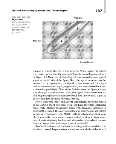
Figure 6-6
Using micromirrors,
the light can be
used as switches in
the networks.
(Lucent)
Mirrors
Source: Lucent
corruption during the conversion process. When looking at optical
conversion, we see that the process follows the overall concept shown
in Figure 6-7. Here, the electrical signal is converted into an optical
signal at the left side of the figure. Next, the signal moves across the
network; at a regenerator, the signal is then converted from light
back into an electrical signal, regenerated, and reconverted back into
a photonic signal (light). Now, at the far left side of the figure, we pro-
ceed through a cross-connect. Here, the signal is extracted from an
add-drop multiplexer and converted back into an electrical signal to
be switched into the next fiber network leg.
Nortel Networks (Xros) and Lucent Technologies have both chosen
to use MEMS-based switches. With long-haul providers (including
those with Internet backbones) faced with dramatic increases in
bandwidth demand, the race to develop and bring to market optical
switching technologies is on. MEMS is the first technology that looks
like it meets the basic requirements, include scaling to large num-
bers of ports, relatively low loss and attenuation throughout the sys-
tem, and support for a wide spectrum of bandwidth.
Xros’s silicon-based micromirror technology will enable data to be
switched through large-scale optical networks entirely in the form of