
Page 287 - Optofluidics Fundamentals, Devices, and Applications
P. 287
Optofluidic Micr oscope 261
with a thin metal layer and that has a line of small apertures that are
etched onto the metal layer. Each aperture should be situated at the
center of each sensor pixel. The sensor pixel will then be sensitive
only to light transmitted through the aperture. By placing a target
object on top of the grid, we can then obtain a sparsely sampled image
of the object (Fig. 11-1a). We can “fill in” the image by raster-scanning
the object over the grid (or equivalently, raster-scanning the grid
under the object) and compositing the time-varying transmissions
through the apertures appropriately (Fig. 11-1b). We can see that in
this case, the resolution is fundamentally determined by the aperture
size and not the pixel size. Therefore, by choosing the appropriate
aperture size, we can achieve high resolution.
This imaging strategy can be simplified by tilting the aperture
grid slightly and replacing the raster-scan pattern with a single linear
Image
Scheme
(a)
(b)
Raster scan
y
(c)
x Translation
θ
Flow
y
(d)
x θ
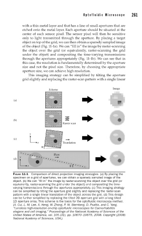
FIGURE 11-1 Comparison of direct projection imaging strategies. (a) By placing the
specimen on a grid of apertures, we can obtain a sparsely sampled image of the
object. (b) We can “fi ll in” the image by raster-scanning the object over the grid (or
equivalently, raster-scanning the grid under the object) and compositing the time-
varying transmissions through the apertures appropriately. (c) This imaging strategy
can be simplifi ed by tilting the aperture grid slightly and replacing the raster-scan
pattern with a single linear translation of the object across the grid. (d) This design
can be further simplifi ed by replacing the tilted 2D aperture grid with a long tilted
1D aperture array. This scheme is the basis for the optofl uidic microscopy method.
(X. Cui, L. M. Lee, X. Heng, W. Zhong, P. W. Sternberg, D. Psaltis, and C. Yang,
“Lensless high-resolution on-chip optofl uidic microscopes for Caenorhabditis
elegans and cell imaging,” Proceedings of the National Academy of Sciences of the
United States of America, vol. 105 (31), pp. 10670–10675, 2008. Copyright (2008)
National Academy of Sciences, USA.)