
Page 45 - Optofluidics Fundamentals, Devices, and Applications
P. 45
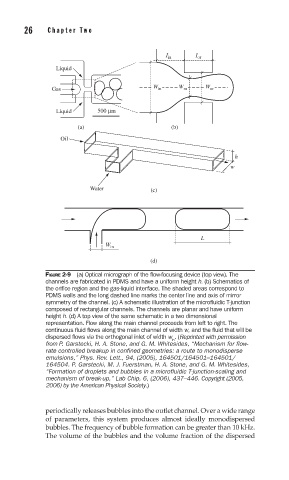
26     Cha pte r  T w o


                                                I in    I or
                  Liquid


                                             W      W      W
                 Gas                          in     m      or

                  Liquid     500 μm
                        (a)                       (b)
                   Oil


                                                                   h
                                                                  w


                           Water            (c)


                                                          L
                                W in
                                            (d)

               FIGURE 2-9  (a) Optical micrograph of the fl ow-focusing device (top view). The
               channels are fabricated in PDMS and have a uniform height h. (b) Schematics of
               the orifi ce region and the gas-liquid interface. The shaded areas correspond to
               PDMS walls and the long dashed line marks the center line and axis of mirror
               symmetry of the channel. (c) A schematic illustration of the microfl uidic T-junction
               composed of rectangular channels. The channels are planar and have uniform
               height h. (d) A top view of the same schematic in a two dimensional
               representation. Flow along the main channel proceeds from left to right. The
               continuous fl uid fl ows along the main channel of width w, and the fl uid that will be
               dispersed fl ows via the orthogonal inlet of width w . (Reprinted with permission
                                                  in
               from P. Garstecki, H. A. Stone, and G. M. Whitesides, “Mechanism for flow-
               rate controlled breakup in confined geometries: a route to monodisperse
               emulsions,” Phys. Rev. Lett., 94, (2005), 164501/164501–164501/
               164504. P. Garstecki, M. J. Fuerstman, H. A. Stone, and G. M. Whitesides,
               “Formation of droplets and bubbles in a microfluidic T-junction-scaling and
               mechanism of break-up,” Lab Chip, 6, (2006), 437–446. Copyright (2005,
               2006) by the American Physical Society.)


               periodically releases bubbles into the outlet channel. Over a wide range
               of parameters, this system produces almost ideally monodispersed
               bubbles. The frequency of bubble formation can be greater than 10 kHz.
               The volume of the bubbles and the volume fraction of the dispersed