
Page 305 - Organic Electronics in Sensors and Biotechnology
P. 305
282 Chapter Seven
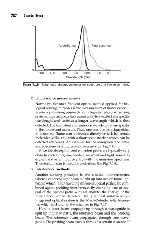
FIGURE 7.15 Schematic absorption/emission spectrum of a fl uorescent dye.
2. Fluorescence measurements
Nowadays the most frequent optical method applied for bio-
logical sensing purposes is the measurement of fluorescence. It
is also a promising approach for integrated photonic sensing
systems. In principle, a fluorescent analyte is excited at a specific
wavelength and emits at a longer wavelength which is then
detected. The excitation and emission wavelengths are specific
to the fluorescent molecule. Thus, one uses this technique either
to detect the fluorescent molecules directly or to label certain
molecules, cells, etc., with a fluorescent marker which can be
detected afterward. An example for the absorption and emis-
sion spectrum of a fluorescent dye is given in Fig. 7.15.
Since the absorption and emission peaks are typically very
close to each other, one needs a narrow-band light source to
excite the dye without overlap with the emission spectrum.
Therefore, a laser is used for excitation. See Fig. 7.16.
3. Interference methods
Another sensing principle is the classical interferometer,
where a coherent light beam is split up into two or more light
beams which, after traveling different optical paths, are com-
bined again, yielding interference. By changing one or sev-
eral of the optical paths with an analyte, the change of the
interference can be detected. The type most suitable for an
integrated optical system is the Mach-Zehnder interferome-
ter, which is shown in the schemes in Fig. 7.17.
Here, a laser beam propagating through a waveguide is
split up into two parts, the reference beam and the probing
beam. The reference beam propagates through one wave-
guide. The probing beam travels through a certain distance of