
Page 122 - PDA Robotics Using Your Personal Digital Assistant to Control Your Robot
P. 122
PDA 05 5/30/03 11:35 AM Page 98
PDA Robotics
tery pack. The grounds are, and must be, connected (common ground).
The circuit’s block diagram is shown in Figure 5.42.
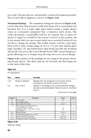
Maximum Ratings. The maximum ratings are shown in Figure 5.43.
I really like this chip because it will shut down if it is overloaded and
becomes hot. It is a nasty sight (and smell) seeing a smoke plume
when an overloaded component like a transistor melts down. The
L298 can handle a respectable load for its compact size (3 amps, 25
watts). It might be overkill for the motors it drives in this project, but
it also means that you can connect much more powerful motors if you
decide to change the design. The enable feature and the 2-pin logic
lines (with a wide voltage range of –0.3 to 7 V) per side makesa great
logic interface. ST microelectronics and Protel provide the footprint
and profile for use in the Protel 98 and Protel DXP circuit design pro-
grams allowing you to simply drop the chip into your circuit design.
Figure 5.44 a picture of the package we are using in the project show-
ing the pin layout. The short pins are set forward, and the longer are
to the back of the chip.
Table 5.5
Pin Descriptions
Pins Name Function
1,15 Sense A; Sense B Between this pin and ground is the sense resistor
connected to control the current of the load.
2,3 Out 1; Out 2 Outputs of the Bridge A; the current that flows through
the load connected between these two pins is monitored
at pin 1.
(continued on next page)
Figure 5.43
Maximum ratings.
98