
Page 36 - PDA Robotics Using Your Personal Digital Assistant to Control Your Robot
P. 36
PDA 01 5/30/03 9:09 AM Page 12
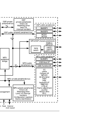
DSP public peripherals McBSP1 McBSP3 MCSI1 MCSI2 MPU/DSP shared peripherals Mailbox GPIO I/F UART1 TIPB UART2 switch UART3 IrDA MPU public peripherals McBSP2 USB Host I/F USB Function I/F I 2 C µWire Camera I/F MPUIO 32-kHz timer PWT PWL keyboard I/F MMC/SD LPG x2 Frame adjustment counter HDQ/1-Wire RTC
DSP private peripherals timers (3) Watchdog timer level 1/2 interrupt handlers DSP public (shared) peripheral bus MPU public peripherals bus 32 MPU private peripherals bus MPU private peripherals Timers (3) Watchdog timer Level 1/2 interrupt handlers Configuration registers Device identification
DSP private peripheral bus 16 16 MPU peripheral bridge External Reset Clock clock request
TMS320C55x DSP (instruction cache, SARAM, DARAM, DMA, H/W accelerators) 16 MPU interface 32 32 32 System DMA controller 32 Clock and reset management OSC OSC 32 MHz 12 MHz
MPU Bus
32
32
32
32
16 LCD I/F
32
DSP MMU Memory interface traffic controller (TC) MPU core (TI925T) (instruction cache, data cache, MMU) ETM9
32 32
OMAP5910 E M I F F E M I F F I M I F JTAG/ emulation I/F Block diagram of an OMAP processor.
16 16 32 SRAM 1.5M bits
Flash and SRAM memories SDRAM memories Figure 1.6
12