
Page 43 - PDA Robotics Using Your Personal Digital Assistant to Control Your Robot
P. 43
PDA 02 5/27/03 8:20 AM Page 19
Chapter 2 / Robotic System Overview
can provide local on-card regulation, eliminating the distribution
problem associated with single point regulation. Each type employs
internal current limiting, thermal shutdown, and safe area protection,
making it essentially indestructible. If adequate heat sinking is pro-
vided, they can deliver over 1A output current. Although designed
primarily as fixed voltage regulators, these devices can be used with
external components to obtain adjustable voltage and currents. Note:
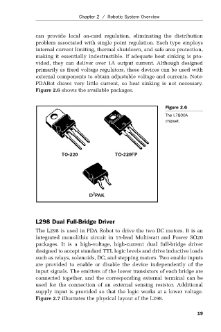
PDABot draws very little current, so heat sinking is not necessary.
Figure 2.6 shows the available packages.
Figure 2.6
The L7800A
chipset.
L298 Dual Full-Bridge Driver
The L298 is used in PDA Robot to drive the two DC motors. It is an
integrated monolithic circuit in 15-lead Multiwatt and Power SO20
packages. It is a high-voltage, high-current dual full-bridge driver
designed to accept standard TTL logic levels and drive inductive loads
such as relays, solenoids, DC, and stepping motors. Two enable inputs
are provided to enable or disable the device independently of the
input signals. The emitters of the lower transistors of each bridge are
connected together, and the corresponding external terminal can be
used for the connection of an external sensing resistor. Additional
supply input is provided so that the logic works at a lower voltage.
Figure 2.7 illustrates the physical layout of the L298.
19