
Page 106 - Petroleum and Gas Field Processing
P. 106
1. Check for gas capacity constraint, Eq. (18):
Q g TZ g c d
1=2
LD ¼ 422
P o g d m
1=2
15 520 0:84 3:708 1:1709
¼ 422
1000 53:03 3:708 100
LD ¼ 82:04 ðE3Þ
2. Check for oil capacity (retention time), Eq. (20):
2
D L ¼ 1:428Q o t ¼ 1:428 3000 3
2
D L ¼ 12;852 ðE4Þ
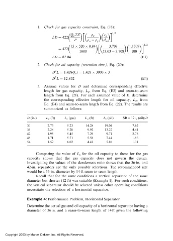
3. Assume values for D and determine corresponding effective
length for gas capacity, L g , from Eq. (E3) and seam-to-seam
length from Eq. (21). For each assumed value of D, determine
the corresponding effective length for oil capacity, L o , from
Eq. (E4) and seam-to-seam length from Eq. (22). The results are
summarized as follows:
D (in.) L g (ft) L s (gas) L o (ft) L s (oil) SR ¼ 121 s (oil)/D
30 2.73 5.23 14.28 19.04 7.62
36 2.28 5.28 9.92 13.22 4.41
42 1.95 5.45 7.29 9.71 2.78
48 1.71 5.71 5.58 7.44 1.86
54 1.52 6.02 4.41 5.88 1.31
Comparing the value of L s for the oil capacity to those for the gas
capacity shows that the gas capacity does not govern the design.
Investigating the values of the slenderness ratio shows that the 36-in. and
42-in. separators are the only possible selections. The recommended size
would be a 36-in. diameter by 14-ft seam-to-seam length.
Recall that for the same conditions a vertical separator of the same
diameter but shorter (12-ft) was suitable (Example 1). For such conditions,
the vertical separator should be selected unless other operating conditions
necessitate the selection of a horizontal separator.
Example 4: Performance Problem, Horizontal Separator
Determine the actual gas and oil capacity of a horizontal separator having a
diameter of 36 in. and a seam-to-seam length of 14 ft given the following
Copyright 2003 by Marcel Dekker, Inc. All Rights Reserved.