
Page 363 - Petrophysics 2E
P. 363
CENTRIFUGE MEASUREMENT OF CAPILLARY PRESSURE 33 1
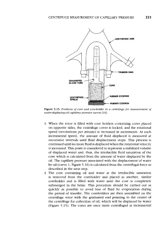
Figure 5.15. Positions of core and core-bolder in a centrifuge for measurement of
watw-displacing-oil capillary pressure curves [I 61.
3. When the rotor is filled with core holders containing cores placed
on opposite sides, the centrifuge cover is locked, and the rotational
speed (revolutions per minute) is increased in increments. At each
incremental speed, the amount of fluid displaced is measured at
successive intervals until fluid displacement stops. This process is
continued until no more fluid is displaced when the rotational velocity
is increased. This point is considered to represent a stabilized volume
of displaced water and, thus, the irreducible fluid saturation of the
core which is calculated from the amount of water displaced by the
oil. The capillary pressure associated with the displacement of water
by oil (curve 1, Figure 5.16) is calculated from the centrifugal force as
described in the next step.
4. The core containing oil and water at the irreducible saturation
is removed from the coreholder and placed in another, similar
coreholder and is filled with water until the core is completely
submerged in the brine. This procedure should be carried out as
quickly as possible to avoid loss of fluid by evaporation during
the period of transfer. The coreholders are then assembled on the
centrifuge rotor with the graduated end pointing to the center of
the centrifuge for collection of oil, which will be displaced by water
(Figure 5.15). The cores are once more centrifuged at incremental