
Page 205 - Phase Space Optics Fundamentals and Applications
P. 205
186 Chapter Five
On the other hand, if we use the complex amplitude transmittance of
Eq. (5.56) in the case of a single phase element, except for a normal-
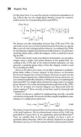
ization factor, the corresponding defocused MTF is
|H( ; W 2,0 )|
∞
2
W 2,0
= exp i2 (3
) + 2
−∞
× rect d (5.59)
2 −| |
We discuss next the relationship between Eqs. (5.58) and (5.59). On
one hand, we can set a coherent optical processor that uses as a spatial
filter a pair of cubic conjugate phase elements. According to Eq. (5.58),
by introducing a displacement between both elements, we generate a
quadratic-phase delay within the integral, which is used for evaluat-
ing the PSF.
On the other hand, under noncoherent illumination, we can gather
images using a single cubic phase element as the spatial filter. Ac-
cording to Eq. (5.59), due to the autocorrelation operation, we also
generate a quadratic-phase delay within the integral, which is used
for evaluating the MTF.
Hence, in the above two cases, we are able to generate a quadratic-
phase delay within a Fourier integral. In this manner, we transform
the Fourier integral into a Fresnel integral. Of course, in each case the
Fresnel integral appears for a different physical reason. However, it is
convenienttoexploitthissimilaritywiththepurposeofvisualizingthe
defocused MTF of a single-phase element by using a pair of conjugate
phase elements. It is worth remarking that the expression in Eq. (5.59),
for the AF in terms of a Fresnel integral, was discovered early by
radar engineers. 58 More recently, it has been used by Somayaji and
Christensen. 65
Finally, we discuss a method for implementing optically a tunable
wavefront coding mask. We assume that the complex amplitude trans-
mittance of a single-phase element is
4
T( ) = exp i2
rect (5.60)
2
We employ
again to represent the maximum phase delay, at the edge
of the pupil aperture. The two-dimensional version of Eq. (5.60) was
presented by Lopez-Gil et al. for generating spherical aberration. 64
Here we consider that at the pupil aperture we have a pair of
quadratic-phase elements, which are laterally displaced in opposite
directions, say, by /2. We also assume that the optical system suffers