
Page 277 - Phase Space Optics Fundamentals and Applications
P. 277
258 Chapter Eight
p
P(z, ξ )
1
T(z, ξ ) – T(z, ξ )
0
1
P(z, ξ )
0
X(z, ξ ) X(z, ξ ) x
0 1
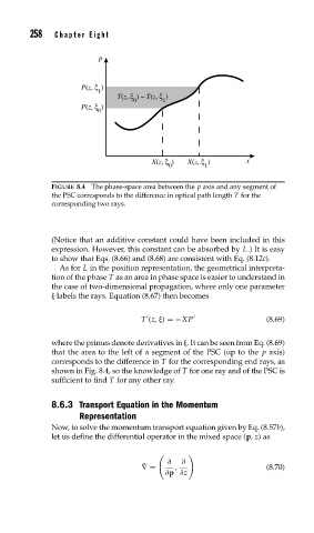
FIGURE 8.4 The phase-space area between the p axis and any segment of
the PSC corresponds to the difference in optical path length T for the
corresponding two rays.
(Notice that an additive constant could have been included in this
expression. However, this constant can be absorbed by L.) It is easy
to show that Eqs. (8.66) and (8.68) are consistent with Eq. (8.12c).
As for L in the position representation, the geometrical interpreta-
tion of the phase T as an area in phase space is easier to understand in
the case of two-dimensional propagation, where only one parameter
labels the rays. Equation (8.67) then becomes
T (z, ) =−XP (8.69)
where the primes denote derivatives in . It can be seen from Eq. (8.69)
that the area to the left of a segment of the PSC (up to the p axis)
corresponds to the difference in T for the corresponding end rays, as
shown in Fig. 8.4, so the knowledge of T for one ray and of the PSC is
sufficient to find T for any other ray.
8.6.3 Transport Equation in the Momentum
Representation
Now, to solve the momentum transport equation given by Eq. (8.57b),
let us define the differential operator in the mixed space (p,z)as
∂ ∂
˜ ∇= , (8.70)
∂p ∂z