
Page 11 - Phase-Locked Loops Design, Simulation, and Applications
P. 11
MIXED-SIGNAL PLL BUILDING BLOCKS Ronald E. Best 10
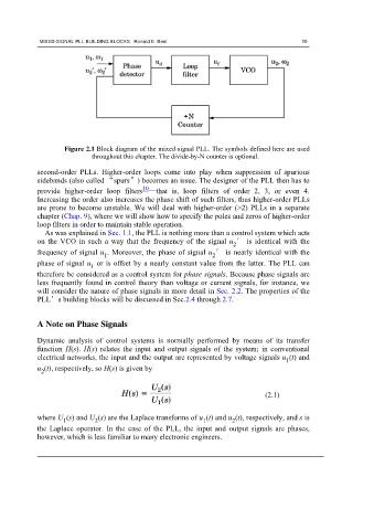
Figure 2.1 Block diagram of the mixed-signal PLL. The symbols defined here are used
throughout this chapter. The divide-by-N counter is optional.
second-order PLLs. Higher-order loops come into play when suppression of spurious
sidebands (also called “spurs”) becomes an issue. The designer of the PLL then has to
10
provide higher-order loop filters —that is, loop filters of order 2, 3, or even 4.
Increasing the order also increases the phase shift of such filters, thus higher-order PLLs
are prone to become unstable. We will deal with higher-order (>2) PLLs in a separate
chapter (Chap. 9), where we will show how to specify the poles and zeros of higher-order
loop filters in order to maintain stable operation.
As was explained in Sec. 1.1, the PLL is nothing more than a control system which acts
on the VCO in such a way that the frequency of the signal u ′ is identical with the
2
frequency of signal u . Moreover, the phase of signal u ′ is nearly identical with the
1 2
phase of signal u or is offset by a nearly constant value from the latter. The PLL can
1
therefore be considered as a control system for phase signals. Because phase signals are
less frequently found in control theory than voltage or current signals, for instance, we
will consider the nature of phase signals in more detail in Sec. 2.2. The properties of the
PLL’s building blocks will be discussed in Sec.2.4 through 2.7.
A Note on Phase Signals
Dynamic analysis of control systems is normally performed by means of its transfer
function H(s). H(s) relates the input and output signals of the system; in conventional
electrical networks, the input and the output are represented by voltage signals u (t) and
1
u (t), respectively, so H(s) is given by
2
(2.1)
where U (s) and U (s) are the Laplace transforms of u (t) and u (t), respectively, and s is
2
1
2
1
the Laplace operator. In the case of the PLL, the input and output signals are phases,
however, which is less familiar to many electronic engineers.