
Page 7 - Phase-Locked Loops Design, Simulation, and Applications
P. 7
INTRODUCTION TO PLLS Ronald E. Best 5
u (t) is equal to the average phase of the input signal u (t). Therefore, we can state that the
2 1
PLL is able to detect a signal that is buried in noise. These simplified considerations have
shown that the PLL is nothing but a servo system that controls the phase of the output signal
u (t).
2
As shown in Fig. 1.2, the PLL was always able to track the phase of the output signal to the
phase of the reference signal; this system was locked at all times. This is not necessarily the
case, however, because a larger frequency step applied to the input signal could cause the
system to “unlock.” The control mechanism inherent in the PLL will then try to become
locked again, but will the system indeed lock again? We shall deal with this problem in the
following chapters. Basically two kinds of problems must be considered:
■ The PLL is initially locked. Under what conditions will the PLL remain locked?
■ The PLL is initially unlocked. Under what conditions will the PLL become locked?
If we try to answer these questions, we notice that different PLLs behave quite differently in
this regard. We find there are some fundamentally different types of PLLs. We will identify
these various types in Sec. 1.3.
Historical Background
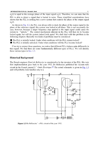
The French engineer Henri de Bellescize is considered to be the inventor of the PLL. His very
first implementation goes back to the year 1932. De Bellescize published his vacuum tube
22
circuit in the French journal L’Onde Electrique. The actual schematic is given in Fig. 1.3
and will probably look familiar only to a
Figure 1.3 De Bellescize’s PLL circuit of the year 1932.