
Page 5 - Phase-Locked Loops Design, Simulation, and Applications
P. 5
INTRODUCTION TO PLLS Ronald E. Best 4
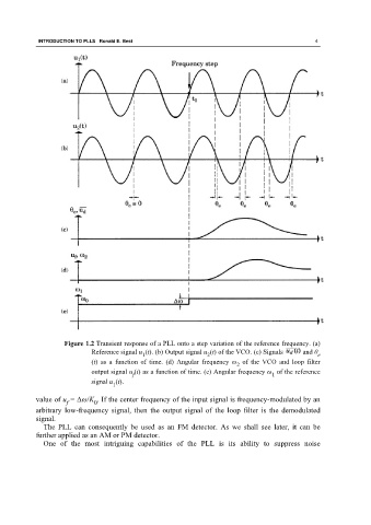
Figure 1.2 Transient response of a PLL onto a step variation of the reference frequency. (a)
Reference signal u (t). (b) Output signal u (t) of the VCO. (c) Signals and θ e
1
2
(t) as a function of time. (d) Angular frequency ω of the VCO and loop filter
2
output signal u (t) as a function of time. (e) Angular frequency ω of the reference
f 1
signal u (t).
1
value of u = Δω/K . If the center frequency of the input signal is frequency-modulated by an
f 0
arbitrary low-frequency signal, then the output signal of the loop filter is the demodulated
signal.
The PLL can consequently be used as an FM detector. As we shall see later, it can be
further applied as an AM or PM detector.
One of the most intriguing capabilities of the PLL is its ability to suppress noise