
Page 12 - Phase-Locked Loops Design, Simulation, and Applications
P. 12
MIXED-SIGNAL PLL BUILDING BLOCKS Ronald E. Best 11
To see what phase signals really are, we assume for the moment that both input and output
signals of the PLL (Fig. 2.1) are sine waves:
(2.2)
The information carried by these signals is neither the amplitude (U or U , respectively)
10
20
nor the frequency (ω or ω ′, respectively) but the phases θ (t) and θ ′(t).
1 2 1 2
Note: Because we used the symbol ω ′ for the radian frequency at the output of the down
2
scaler (Fig. 2.1), we use the symbol θ ′ for the phase of signal u ′ and not θ ; the latter is
2
2
2
used to specify the phase of the VCO output signal u .
2
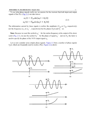
Let us now consider some simple phase signals. Figure 2.2 lists a number of phase signals
θ (t), which are frequently used to excite a PLL. Figure 2.2a shows
1