
Page 195 - Phase-Locked Loops Design, Simulation, and Applications
P. 195
MIXED-SIGNAL PLL APPLICATIONS PART 1: INTEGER-N FREQUENCY 120
SYNTHESIZERS Ronald E. Best
can switch their output frequency more rapidly than conventional integer-N synthesizers.
Integer-N Frequency Synthesizers without Prescalers
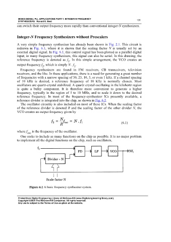
A very simple frequency synthesizer has already been shown in Fig. 2.1. This circuit is
redrawn in Fig. 6.1, where it is shown that the scaling factor N is usually set by an
external digital signal. In Fig. 6.1, this control signal has been plotted as a parallel digital
input; in many frequency synthesizers, this signal can also be serial. In this drawing, the
reference frequency is denoted as f . In this simple arrangement, the VCO creates an
1
output frequency f , which is simply N . f .
1
2
Frequency synthesizers are found in FM receivers, CB transceivers, television
receivers, and the like. In these applications, there is a need for generating a great number
of frequencies with a narrow spacing of 50, 25, 10, 5, or even 1 kHz. If a channel spacing
of 10 kHz is desired, a reference frequency of 10 kHz is normally chosen. Most
oscillators are quartz-crystal stabilized. A quartz crystal oscillating in the kilohertz region
is quite a bulky component. It is therefore more convenient to generate a higher
frequency, typically in the region of 5 to 10 MHz, and to scale it down to the desired
reference frequency. In most of the frequency-synthesizer ICs presently available, a
reference divider is integrated into the chip, as shown in Fig. 6.2.
The oscillator circuitry is also included on most of these ICs. When the scaling factor
of the reference divider is denoted R and the scaling factor of the other divider N, the
VCO creates an output frequency given by
(6.1)
where f osc is the frequency of the oscillator.
One seeks to include as many functions on the chip as possible. It is no major problem
to implement all the digital functions on the chip, such as oscillators,
Figure 6.1 A basic frequency synthesizer system.
Printed from Digital Engineering Library @ McGraw-Hill (www.Digitalengineeringlibrary.com).
Copyright ©2004 The McGraw-Hill Companies. All rights reserved.
Any use is subject to the Terms of Use as given at the website.